|
|
|
#1
 10/22/2007, 01:33 AM
|
|||
|
|||
|
Aquasurf your Vortech WWD, the DIY
In this DIY, I demonstrate how to connect Neptune's Aquasurf with the Vortech WWD. It can be completed in about 1.5 to 2 hours by most people and at a cost of less than $10 for the parts.
Theory: The new Vortech WWD uses a 50Kohm POT to vary a 3.3 control voltage to the processor. Depending on the Mode and state of the WWD this POT either sets the pump speed or pulse timing. In this DIY I bias the control voltage coming form the Aquasurf to match the 3.3volts needed to control the WWD. I do this with a 100K POT which is place in a 4-wire In-Line coupler (ILC) usually used for extending phone cords. The ILC is used to connect the Aquasurf to the Vortech. The processor is very small and there is no way to solder a wire to it. For this reason I cut the center pin of the POT disconnecting it from the circuit board and the processor, then put in its place a wire carrying the control voltage coming form the aquasurf. In case there is ever a need to run the Vortech without the Aquasurf, I have devised a simple way to reconnect the WWD POT to the processor by simpley reversing the ILC's connection to the Vortech WWD and it takes all of two seconds to do even if you move slow. The aquasurf has several modes, constant speed, lagoon random, reef-crest and pulse mode. In the constant speed mode the WWDs POT controls the pump speed. The WWD can also can be assigned as a master or slave via the wireless system. Those who have multiple pumps on one end of their tank can use this to their advantage. But most will not use the wireless feature at all. When the Aquasurf is connected to the Vortech WWD, simply put all the WWDs connected to the aquasurf, into the constant speed mode for full control. The Aquasurf has the ability to be powered buy either a wall-wart or buy the device is it controlling. I have opted to have it powered by the WWD. The WWD has a 11.8 volt source that I use to power the aquasurf. This way if you have the battery back-up for the vortech, the aquasurf will keep working in the event of a power failure. You can even program the aquacontroller change the vortech speed in the event of a power failure, helping prolong battery life. Advantages: You have complete and more precise control over the pump. You set the power by a percentage not by guess work like with the little knob. Your results are very easily reproduced. The on and off times are controlled separately with 0.1 sec. resolution again allowing very precise control. This allows you to fine tune your cycle/wave or what ever you can think off. This also means you are not limited to just a few preprogrammed modes but can make custom modes. You can change through your custom modes through out the day automatically. If the power goes out you can have the aqusurf cycle the pumps on and off completely on any cycle you want while the power is out. This will make your battery backup last longer. Anything you can think of with the aquacontroller and the aquasurf are possible with your vortech. If you decide to take your pump off the aquasurf for some reason, no problem. Simply swapping ends with the inline coupler will make the pump work just like factory. Disadvantages: 1. Your Warranty will be VOID if you do this DIY to your WWD. Here are two on my tank, Crankin it UP. 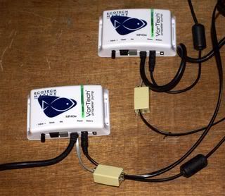 Parts: 1. One 4-wire phone cord of good quality or some phone cord wire and a RJ11 to make your own. 2. 100K-Ohm Horizontal-Style Trimmer (POT), Radio Shack Catalog #: 271-284, $1.29 3. 4-wire Inline Coupler, Radio Shack Catalog #: 279-358 the one on the web is not the same as what was in my store. On the web you want Catalog #: 55021518. 4. A package of 4-Pin RJ11/14 Modular Plugs, Radio Shack Catalog #: 279-384 You can also just go to an electronics shop and have them crimp the connector on for your. 5. Southwestern Bell 2-Way Phone Cord Crimping Tool, Radio Shack Catalog #: 55021766. If you do not have someone else put this connector on for you. I found one at a local hardware store for less than $5. 6. Aquasurf 7. Vortech WWD Step one: Modding the WWD POT In this step you will cut the center pin on the WWD POT and bend it back. Once this is done you will remove what is left of that pin from the circuit board. Modding the WWD POT Before 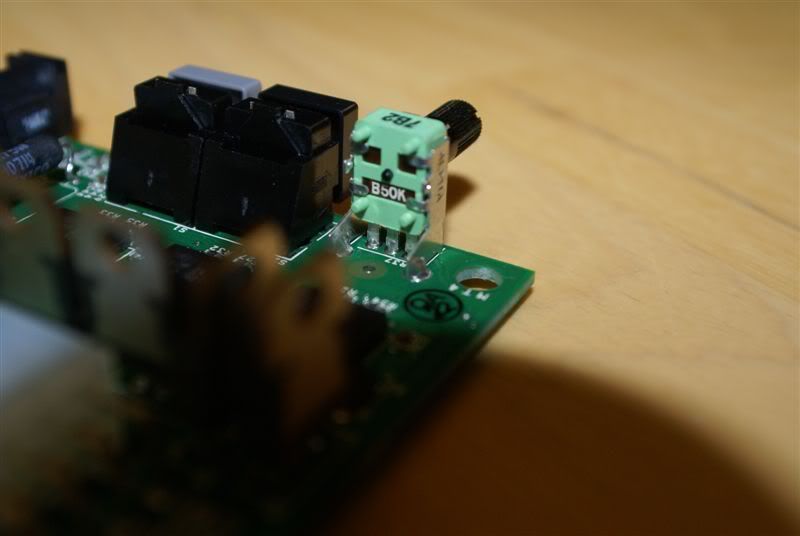 After 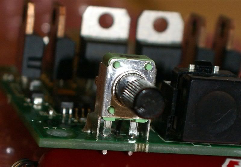 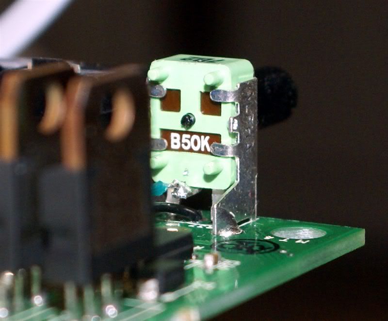 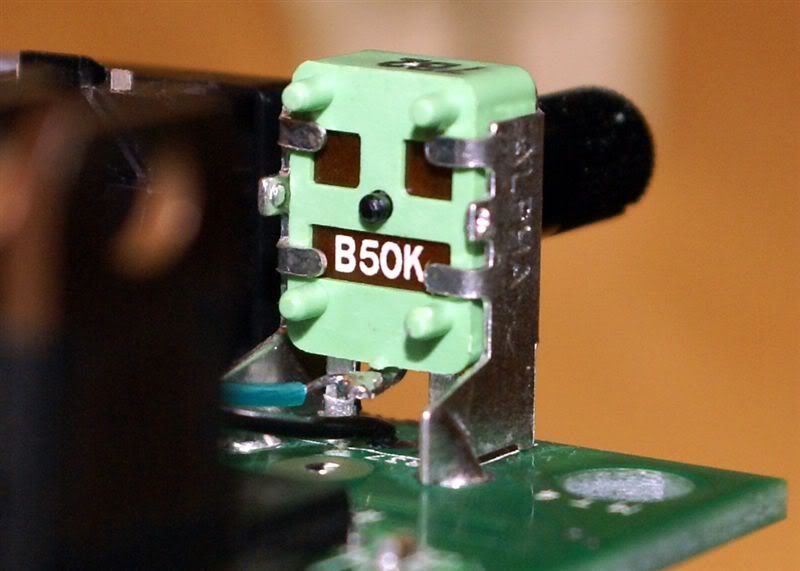 Step Two: Soldering on the Phone cord. Here you will cut 6 inches off an old 4 wire phone cord. You want the end that looks like the photo were the latch part on the rj11 is down, the contact pins are up, the wire is pointed at you and the wires in the connector are black/red/green/yellow left to right. Now solder the wires as shown in the video. Yellow = 11.8 volts at yellow diode, green = WWD POT center pin we just cut and bent up, red = ground at big black resistor, black = control voltage in, to the hole where the center pin of the WWD POT was. Then zip tie the cord to the black resistor. You are now ready to put the Driver case together. Soldering on the Phone Cord 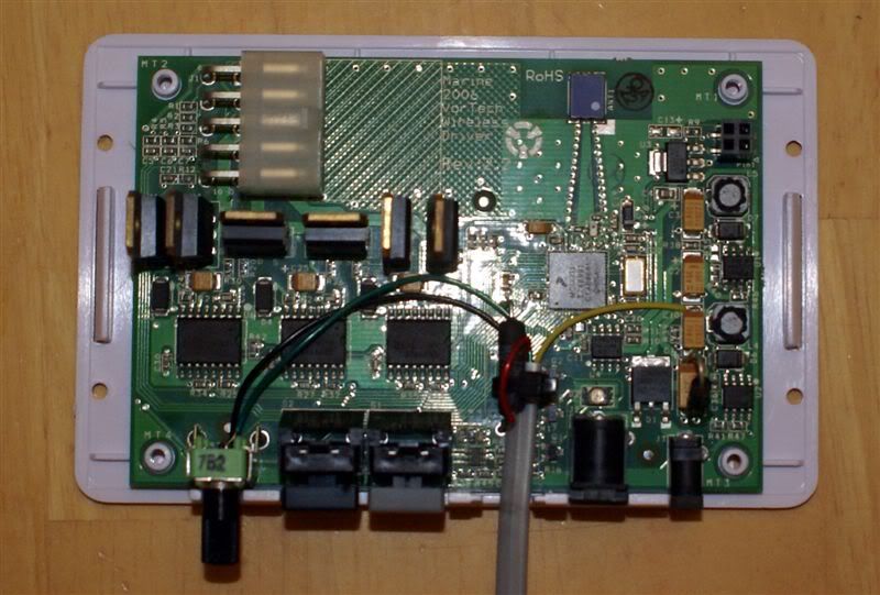 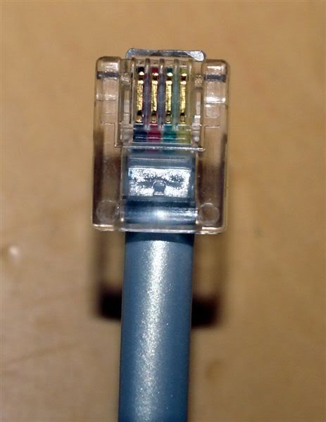
|
|
#2
10/22/2007, 01:34 AM
|
|||
|
|||
|
Step three: Modding the 4-wire In-Line Coupler (ILC)
For the third step you will install the 100K Bias POT in the ILC and rearrange the wires to make it a crossover connector. Easier done than described, see the photo, video and wiring diagram. Modding the In-Line Coupler (Part1) Modding the In-Line Coupler (Part2) Here are two wiring diagrams to show what the ILC is doing and how it is wired. Not the circle with the line in it is the bias POT. Aquasurfing your Vortech. ILC connected to both the vortech and Aquasurf 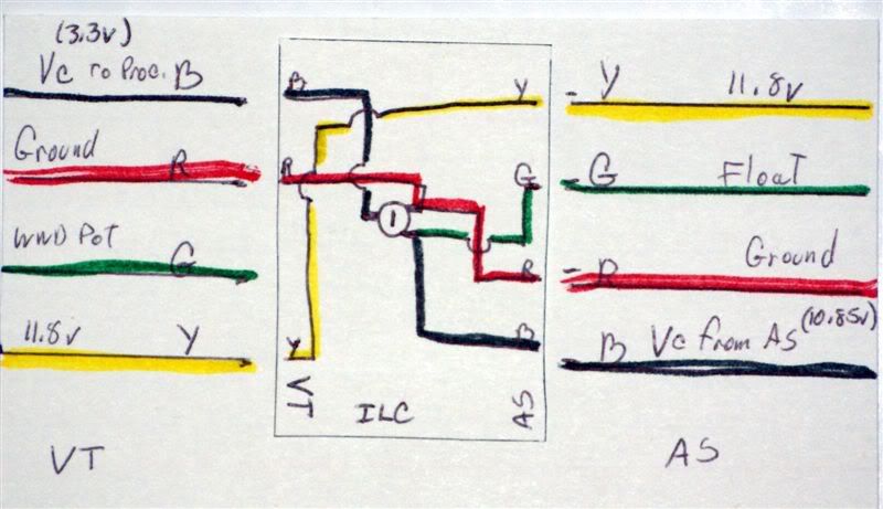 Stock Vorteching, Aquasurf not connected and the ILC's Aquacontroller end connected to the vortech. 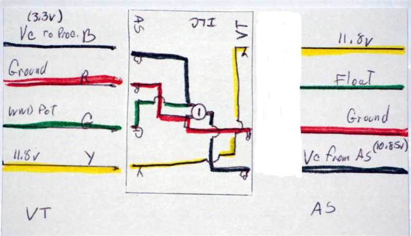 When done, it should look like this. 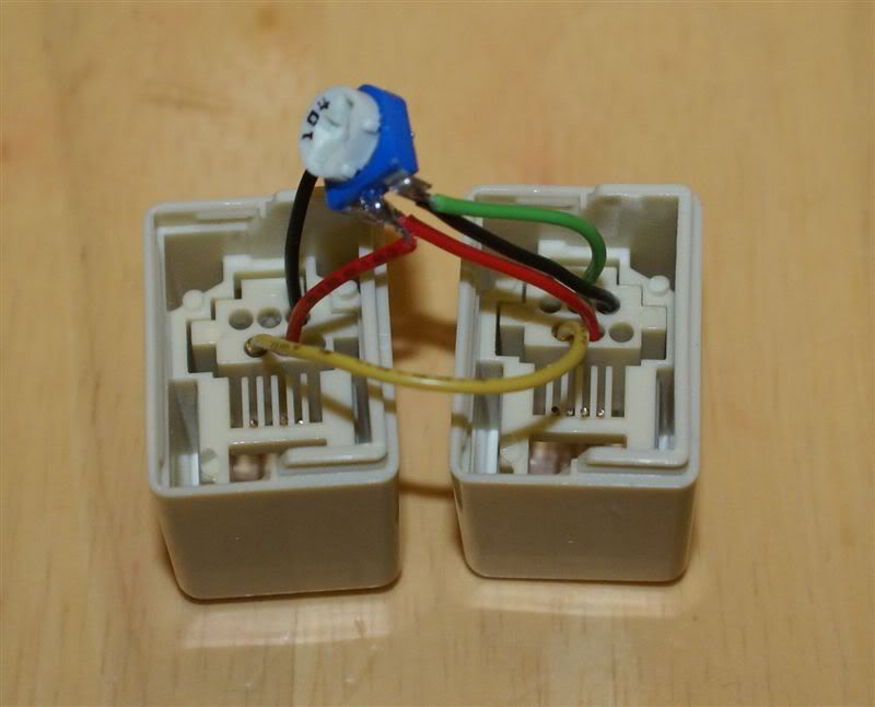 After snapping the ILC back together. 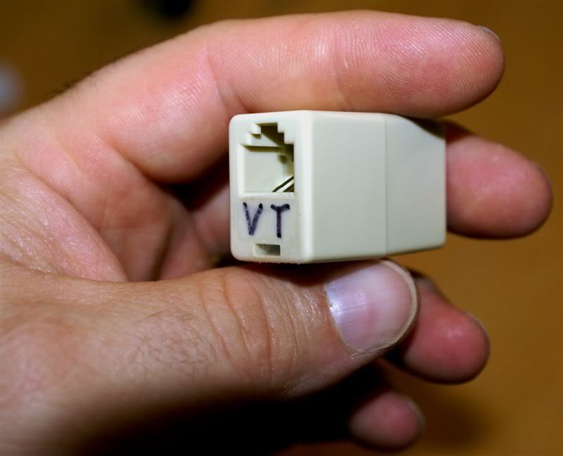 Step four: Calibrate the Bias POT Here you calibrate the Bias POT to bias the control voltage (Vc) so that the ~ 10.85v coming from the aquasurf is bias to ~ 3.3v. First you want to adjust the bias POT so the measured resistance between the pin where the black and green wires connect and the center pin equals ~ 2.15x that as measured between the pin where the red ground wires connect, to the center/output pin. IN my case it was ~64.1Kohm / ~29.9Kohm = 2.14. After final installation, you can fine tune the output pin to 3.3 volts if you like but this method will get you very close. Calibrating the Bias POT Step five: Crimp on an RJ11 to the Aquasurf cable. Simpley cut the stock connector off the Aquasurf cable at the vortech end and Use the RJ11 crimp on tool to put the RJ11 on it. Make sure to have the yellow wire to the right as in the photo. You can have a local phone/computer company do it for you also. Now when you have the vortech plugged into the VT side and the Aquasurf plugged into the AS you are aquasurfing your Vortech. If for some reason you loose you mind and want to use the Vortech in it's stock configuration just plug the vortech into the AS side and the WWD's POT is functional again. Discussion: The new WWD is a stand alone or slave driver that communicates via a "wireless" interface with other driver slaved to it. I personally do not care for using the wireless part. When first trying out the wireless feature with two drivers 2 foot apart they had some trouble communicating as evident by the frequent pulse timing variations in pulse mode. To be fair to the WWD, I also have a linksys wireless access point connected to my Aquacontroller in the cabinet with the drivers. It has a great deal more power output in the same freq. range and may be a source of interference. ETM says the range of these WWDs is 10" max and line of site. As far as the modes of these new drivers go, if I want to change modes I have to do it manually by reaching in the cabinet. In this day of automation I do not wan to have to do that and cannot do that throughout the day without this DIY. After setting it for a good wave in my tank using the pule mode, I have to reset it and tweak it again if I switch out of it. Again not needed with this DIY. If I were not able to do this DIY I would probably only use the pules mode most of the time. When I ordered the WWDs I thought there would be no need for a DIY but I was mistaken. I wanted more control (modes I design and determine the time and duration they come on) over my pumps with my aquacontroller. So, I DIYed the WWD last week on 2 of my 4 drivers. I had one driver come in with an issue and needed replacing. I felt it was important to fully test each driver over a few days to make sure they were tip top before I voided the warranty. Kind of a burn in period. The replacement will be here today. Thanks to Tim for fast service. Do I think someone with old drivers who wants to control their Vortech with an aquacontroler/aquasurf combo need to go out and buy the WWD. No I don't. I feel both work well with the aquasurf. There are a few advantages with the new WWD controlled by the aquasurf that I personally would not pay $75 per driver for. But I am always looking to do something good for less money.  I hope you enjoy this DIY and please post any questions, here in the thread.
__________________
Giovanni _____________________ For my "Aquasurf your Vortech WWD, the DIY" thread, Click the little red house up top. . |
|
#3
10/22/2007, 08:24 AM
|
|||
|
|||
|
So with this DIY I could for still run a pulse mode on the Aquasurf to generate a wave but then at night switch into a lower speed or even a gentler wave?
And if the aquasurf does support the pulse mode then i could DIY one unit then have the other wireless slave unit in anti sync (they are on opposite ends) and make my wave with only one DIYed unit?
__________________
Nick Nicks Acrylic Reef MACNA XVIII - Houston, TX Sept 22nd-24th 2006 |
|
#4
10/22/2007, 09:13 AM
|
|||
|
|||
|
ETM says there is a maximum distance of 10 feet on the WWD, not 10 inches.
Second, I know when I first bought my ACIII Pro, there was a limitation on the length of the communication cables. Is this the case with your mod as well? In other words, how close to demand are you when using the WWD to power the AquaSurf. Will there be signal degradation as the distance increases?
__________________
Jonathan--DIBS Breeder and Card carrying member of the Square Skimmer Brigade (Click on the Red House to see my pics garage) |
|
#5
10/22/2007, 09:58 AM
|
|||
|
|||
|
And another question, I am not sure if you or Tim could answer: When I first got my MP-40s there was a stated minimum cycle of > 1 minute. The reasoning behind this was that the Vortech driver needed time to poll the sensors and process a response. So if the unit sparated (no longer a feature) or the temp. got too high, the Vortech wold change speed or shut down.
Since the AquaSurf is capable of < 1 second intervals, will it negate the WWD's ability to sense over temp. conditions and react?
__________________
Jonathan--DIBS Breeder and Card carrying member of the Square Skimmer Brigade (Click on the Red House to see my pics garage) |
|
#6
10/22/2007, 10:59 AM
|
|||
|
|||
|
Nick,
The answer is no. For some reason ETM decided to make it so that the a slave in constant speed mode is always synced even if is shows anitsync. They can easily fix this if they choose with a code update. Jonathan, Thanks for the correction. It was late last night when I finished and proof read it. You are correct 10 ft. I am not sure what the max length is. The aquasurf was built for use with the Tunze pumps which also provide power for it. I know the aquasurf and operate with as little as 6 volts so if we had that much of a voltage drop, you would be a couple houses over. That said there might be other issues with a low control voltage but that would be minimal and if you know you want a long cable can be calibrated out with the bias POT. All that said, It will will be easy to test out as all one needs is the desired length of 4-wire phone cable and another stock in-kine coupler. I will give it a test, how long do you need them to be? As for your second question, you are over thinking this. Before my DIY people were using wave makers that cut the power to the whole unit and thus reset the processor. Since the first DIY to the Vortech I have not done that eliminating that issue and the one of code corruption. There should be no problem the the WWDs processor sensing an over temp states and reacting. I only manipulate a control voltage going into the processor, the processor can choose to ignore/modify it if there is a temp problem just like it would with the control voltage coming from the WWD's on board POT.
__________________
Giovanni _____________________ For my "Aquasurf your Vortech WWD, the DIY" thread, Click the little red house up top. . |
|
#7
10/22/2007, 12:28 PM
|
|||
|
|||
|
Thanks for the reply. That does make sense. In my case, I would need 20 foot communication cables.
__________________
Jonathan--DIBS Breeder and Card carrying member of the Square Skimmer Brigade (Click on the Red House to see my pics garage) |
|
#8
10/22/2007, 06:17 PM
|
|||
|
|||
|
Very impressive mod. I built a 1-wire based reef controller a while ago and considered hacking a DS2890 (1-wire digital pot) into the driver in order to directly control the speed. The major issue I had was the slow response time of the POT changes. Even manually changing the POT takes a couple seconds to change the motor speed. Now that I see what you did here, I may try adding the DS2890 to the new drivers, when I finally get them.
There are quite a few possibilities with what you made here. Steve |
|
#9
10/22/2007, 09:46 PM
|
|||
|
|||
|
Nick,
For some reason I did not answer your first question. Quote:
The answer is yes you can run a pulse mode for waves or what ever you can dream up. You can have a night more that has a smaller wave. I even have a mode to simulate short 15 minute storm to stir things up followed by a very calm period for 20 minutes then back to my regular day mode. The aquasurf will do anything with this pump it will do with a Tunze Sorry I forgot to answer that.
__________________
Giovanni _____________________ For my "Aquasurf your Vortech WWD, the DIY" thread, Click the little red house up top. . Last edited by Giovanni; 10/22/2007 at 09:52 PM. |
|
#10
10/22/2007, 09:52 PM
|
|||
|
|||
|
I would hope that the Eco-Tech guys are able to provide the same mode switching soon, or get together with Curt and build a joint-WWD/AquaSurf...at least one for me dammit!
 OK...here's what I want...a wireless module hooked to my ACIII Pro that will communicate with all the WWDs in the room, provide feedback on pump temp, pump status, and give me the ability to switch modes/programs from my PC...Then I want to be able to sit in front of my tank and mess with the programs while watching the effect FROM THE FRONT...that's not asking too much right?
__________________
Jonathan--DIBS Breeder and Card carrying member of the Square Skimmer Brigade (Click on the Red House to see my pics garage) |
|
#11
10/23/2007, 11:18 AM
|
|||
|
|||
|
Jon, that was more or less what we were promised originally, wasn't it ? (all except being able to do it from the AC III Pro). Even the computer part was alluded to last year (or was that earlier this year ?)
__________________
- Tom |
|
#12
10/23/2007, 12:08 PM
|
|||
|
|||
|
I have no idea at this point Tom. I guess I don't understand why we can only select one mode rather than say pulse 100% daytime, and lagoon 50% night time. I have got to ASSUME that these things are in the pipeline.
Unfortunately, I don't see much advantage to the wireless part at this point. They have two wires coming off them anyway, and it seems to me a daisy-chain like a moonlight array would work just as well without the potential for missed packets. All along I have had a very different concept about what a wireless wave driver would be, but I am certainly interested in how this all plays out. The unfortunate reality is, if I were to follow Calfo's recommendation of 40X turnover, that I might need 18 x MP-40w running in pulse mode at 100%. That's $7,600 and change... 
__________________
Jonathan--DIBS Breeder and Card carrying member of the Square Skimmer Brigade (Click on the Red House to see my pics garage) |
|
#13
10/23/2007, 02:53 PM
|
|||
|
|||
|
More control awaits you both, all that you have to do is step up and DIY your WWDs or even old drivers. Heck I even have a set of the DIYed old drivers I can send someone that are plug and play.
__________________
Giovanni _____________________ For my "Aquasurf your Vortech WWD, the DIY" thread, Click the little red house up top. . |
|
#14
10/23/2007, 09:42 PM
|
|||
|
|||
|
I just lack a controller to "wave" them, although I keep giving serious consideration to a Profilux II Plus. If I am going to spend that kind of money on drivers I might as well channel it into a beefed up, and expandable, controller. Our lil AC Jr has done well, but I am feeling "constrained" lately
 Giovani - I am interested in the ones you already modded, since they have the 5 pin dins to go into the Profilux.. I will shoot you a PM about them (although our budget is already to h*** in a hand basket this year.... but as of today we have enough to pay our property taxes, so that is a relief  ). ).
__________________
- Tom |
|
#15
10/23/2007, 10:21 PM
|
|||
|
|||
|
I just "surfed" over to Neptune;s web site (pun intended) and they say that the AquaSurf works with the AC Jr. So I son't know what I am waiting for
. I am going to see about ordering one from MD tonight, which means I should have it by this weekend. I also didn't know that each AS wqould handle up to 4 pumps.. taht is even better news (I thought they were good for 2 each for osme reason). So that was 2 different, pretty big, misconceptions I was working under *sigh*.
__________________
- Tom |
|
#16
10/23/2007, 10:27 PM
|
|||
|
|||
|
Check Custom Aquatic and with Neptune directly as well. The prices can be somewhat different depending on who you buy from.
__________________
Jonathan--DIBS Breeder and Card carrying member of the Square Skimmer Brigade (Click on the Red House to see my pics garage) |
|
#17
10/23/2007, 11:17 PM
|
|||
|
|||
|
I checked MD so far. I also checked that my AC Jr needs to have it's firmware updated, and mine is the non-serial port version. I am trying to dig up the directions on how to exactly perform that update
.Gionvani -- PM received, let me think about it and get back to you. I wanted to have "stand-bys", but we will see
__________________
- Tom |
|
#18
10/24/2007, 11:23 AM
|
|||
|
|||
|
Giovanni-
Please note, we are only posting this to help you. Any modifications to our board WILL void the warranty. Period. We do not claim that the suggestions made below will prevent damage to our driver board. These are untested recommendations based purely on a superficial look at what you have posted here. 1) Ground is not the top of R36, its the bottom, by using the ground reference off the top of R36, you are offsetting your control signal high by 200 mV which could increase your control signal past the 3.6V max input voltage of our microprocessors pins. 2) You need to make completely sure that there is no way your control signal gets above 3.6V including transients. Your solution is not the most robust for this. We suggest using a 3.3V zener diode on your control signal to make sure of this. 3) You need to make sure your Aquasurf is not pulling more than 50 mA off our 12V supply rail, we did not design this rail to power external devices which means it is not capable of sourcing a lot of current. 4) We suggest against powering the Aquasurf off the 12V rail when on battery power. This could cause stress on some components because the battery backup only provides 12V and our 12V rail goes down to about 10V in this instance, which is okay for our design, but this would likely cause the Aquasurf to pull more current and further stress our supply rail Again- EcoTech Marine takes no responsibility for implementing any of these suggestions. Any modifications made to our driver will void the warranty and potentially damage your driver with or without these suggestions. These suggestions are being made as gesture of our integrity and we hope that you view them as simply that. EcoTech Marine is not in the business of providing engineering support for those who wish to reverse engineer our product. However, we see the value in what you are trying to accomplish and want to aid our customers as best as possible in any endeavors. |
|
#20
10/25/2007, 12:27 AM
|
|||
|
|||
|
Giovani, Do you have the pinout for the AS control ports ? They are supposed to support 2 pumps per plug/port, right ? Ours is on order, so I don't know by looking, but do the control wires that come with the AS have RJ45 ends on them ? What I am really asking is if there was a way to make a complete cable w/o hacking up the one(s) they send with the AS, and also make it so that 4 pumps can be modded/controlled this way ?
Thanks P.S. I think that we will be modding our old drivers this weekend (or maybe just two of them to see how it works out for us.). Once MD has the WWDs in stock and I know we could get them here within a day or two if I smoke the current drivers, then I will likely mod them all.
__________________
- Tom |
|
#21
10/25/2007, 12:45 AM
|
||||
|
||||
|
Tim,
Thanks for going ahead and posting your electrical engineer's formal review of my DIY. I always welcome input from any source that feels they have something to contribute to one of my projects. I do them because I want to help build better gadgets that will help improve this hobby for me. I share them with other so that if anyone has a better or different way of doing them they will post what they know. In this way we all benefit. I consider it a form of TEAM work. Together Everyone Achieves More. That said lets get down to figuring this thing out. Maybe we can all learn something. Quote:
1st photo. Also that statement states a concern about R36 which I believe is a 0.1 ohm 5% 3.75 watt resistor being use a sort of fuse. See photo 2 below. Help me out here on two points as I do not see where your EE is getting 200mv from the circuit or where 3.3volts plus 200mv => 3.6mv. I thought 3.3v plus 0.2v = 3.5v? Also, if in fact I had mistakenly taken my ground form the top of R36, then R36 would be in series with the 100,000 ohm POT being used for Bias as a voltage divider. Now in the example provided in the DIY, my POT resistance was 64,100ohm / and 29,900 ohm and that 0.1 ohm would be need to be added to the 29,900 ohm part of that circuit. That is 29,900 ohm + 0.1 ohm = 29,900.1 ohm. Now if we go to the following link for a Voltage divider circuit and plug in the numbers. R1 = 64,100, R2 = 29,900, V1 = 10.85 volts (per my real world testing with the Aquasurf and vortech DIY) and RL = 1,000,000 (1M ohm) then Vout = 3.4512234 V and Vout (under the load of the processors 1M ohm load) = 3.3822616V. The second one is the actual voltage seen by the processor. Now sub in 29,900.1 ohm and you get Vout = 3.4512312V and Vout (under a the load) = 3.3822691. The difference is a 0.0000075 volt increase seen by the processor. Not quite the 0.200V stated. If R36 was 2,700 ohms then it would be a 0.200 volt difference. Maybe I have the value wrong for R36? In any case I think there is no worries there as I don't believe I have the non-grounded end of R36 if you look closely. Photo 2 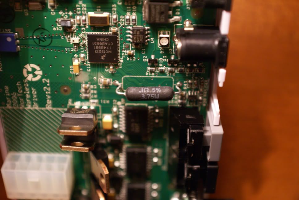 Quote:
In my application I have two drivers on the aquasurf so the aquasurf's load is distributed equally between them and this helps your rail not be overloaded. Also for some reason I keep measuring that 12V rail at 11.8volts before a load is applied and that is on several drivers. Any thought on this? When I get a few days off, I make it a point to measure the current used by the Aquasurf at different voltages. Thanks for the help with the power supply to the Aquasurf. Quote:
I understand that as the manufacturer you are obligated to take a VERY conservative approach. That is a given and no one would blame you for that here in the DIY forums. IMHO you are being very forward looking in your posting here. I thank you for that. I hope you do not feel I am trying to reverse engineer your product. I am not at all interested nor do I have the expertise to build an entire driver. I just want to give more and better control over these wonderful pumps to those who want it. For those of us who are willing to experiment with our drivers at some risk and expense, are rewarded with the control we want now and not later. My DIYed WWD drivers are working great and have been for at lease a week now with no problem. I would not have posted this until I had done it first and let them run under varying conditions to see if they would POP! That said, anyone who is not comfortable with this DIY, Please do not do it. As I stated on the first post it will void your warranty. It also goes without saying for any DIY, if you screw up, you might ruin your $75 WWD and you alone will have to bear that burden. But we all knew that, right? If you find any typos or errors in this post please be kind as I have been up since 5 am, worked a 12 hour shift on 4 hours sleep only to do it again at 5am this morning.
__________________
Giovanni _____________________ For my "Aquasurf your Vortech WWD, the DIY" thread, Click the little red house up top. . |
|
#22
10/25/2007, 12:52 AM
|
|||
|
|||
|
Sparkss,
Good to hear you are stepping up to the plate. You will love the control. Yes you can run up to 4 pumps on the AS and yes I have the in out to build a cable with. Keep us informed of your progress.
__________________
Giovanni _____________________ For my "Aquasurf your Vortech WWD, the DIY" thread, Click the little red house up top. . |
|
#24
10/29/2007, 01:14 AM
|
|||
|
|||
|
I for one am thrilled, amazed, and dumbstruck, that Ecotech would post on this forum. How high class act is that when the manufacturer comes on and offers less a warning, and more advice about the mod to their product. It says a great deal about the high class nature of their organization, and I for one have had my confidence built by their post and openness.
BRAVO Ecotech. I don't have the Cash at the moment to purchase your VTs, but this cements the goal of mine to purchase them. Again Bravo! Aaron
__________________
"Then if there's nothing wrong with me... then there must be something wrong with the universe!" |
|
#25
10/29/2007, 01:15 AM
|
|||
|
|||
|
Oh yeah, and Giovanni, Here's to ya man for having the stones to break into this thing and figure this out. Good job to you too man!
__________________
"Then if there's nothing wrong with me... then there must be something wrong with the universe!" |
|
|


 Linear Mode

