|
|
|
#1
 12/26/2006, 12:45 PM
|
|||
|
|||
|
Auto top off questions
I just hooked up an auto top off to my sump. I'm using a float switch in the sump hooked to a relay which powers my powerhead that pumps the water into my sump from the topoff supply.
Last night after having it hooked up for a while and the sump finishing getting topped off it seemed like the powerhead would kick on for 1-2 seconds, then off again and would do this every 3-4 minutes; maybe longer time frame, but it didn't seem very long in between. I looked in the sump and there wasn't that much water movement. There was some, but not much. Is this normal? I wouldn't think it would be good on the powerhead to turn on and off that frequently and for that short of a time period and really didn't see the need for it to do so. Should I enclose the float inside a jar of some sort with holes in the bottom in hopes this will get rid of any water movement except the raising and lowering of the water and thus the float? I really wish there was a way to allow the water to drop further before the pump kicks in to refill it, but I think this float switch will keep the water level the same for the most part. Any ideas would be appreciated.
__________________
Rick |
|
#2
12/26/2006, 01:30 PM
|
|||
|
|||
|
this is a poor way to describe it, but once you add the water to the sump, it doesn't stay at that exact level, everything evens out in the system and it lowers a bit. so when you add enough water to deactivate the float switch, it balances out in a short while and the level becomes too low again, activating the switch.
you could add a little hysteresis in the system, like have the pump turn on for a minimum of 10 seconds. i don't know how to do that without buying a controller that can do it for you. you could also try a slower pump, like the aqualifter. it's cheap, and only does like 2-3 gallons per hour. the slower rate may give your water level time to adjust. i'd recommend the aqualifter anyways for topoff, for many reasons. like it can run dry safely.
__________________
i'm not a real doctor, i just play one on tv. |
|
#3
12/28/2006, 12:21 PM
|
|||
|
|||
|
What do you need is two floats, one lower than the other, the lower float turns the pump on while the higher float turns it off, this way you can adjust the height between floats to adjust how much water the pump will add at one time.
__________________
Did I write what I wrote? What the heck am I talking about! Well..... Nevermind. |
|
#4
12/28/2006, 12:32 PM
|
|||
|
|||
|
j...
why dont you explain how, so rick doesnt spend the next 2 hours trying to figuer it out. |
|
#5
12/28/2006, 01:03 PM
|
|||
|
|||
|
OK here is a diagram of one way to do it using low voltage (The safest) at the float terminals.
When the water reaches teh low level float the relay energize and actuates either your solenoid or your pump and also uses one of the contacts to latch the relay energized as the water rises and the float opens again. The relay stay energized until the water reaches the higher level float then it de-energize and turns off. The switch allows you to turn it on even if the water is not at the lower level but even on manual the uper float will turn it off. If you leave the switch on manual the system will operate as you have it today using only the higher level float as ON/OFF. The light will turn on whenever water is being added to the sump. If you have a 120 V coil relay you do not need the 12 V adapter and the 120V termianlsc an be connected directly to the 12V circuit although for safety I recommend modifying it to 12 V, you do not want the potential for a 120V short circuit to the aquarium water via the floats. 
__________________
Did I write what I wrote? What the heck am I talking about! Well..... Nevermind. |
|
#6
12/28/2006, 02:31 PM
|
|||
|
|||
|
Quote:
|
|
#7
12/28/2006, 04:14 PM
|
|||
|
|||
|
I would enclose them like this or something similar, I have these on the main tank with lots of surface flow and they don't come on often, just when need it. The holes are at the bottom and at the top.
__________________
2 yellows tail damsels, yellow watchman goby, tail spot blennie, purple pseudocromis, starry blennie, 2 clowns, 1 black clown, mandarine |
|
#8
12/28/2006, 05:36 PM
|
|||
|
|||
|
hey nice job j
would have done it myself but didnt want to steal your thunder 
|
|
#10
12/28/2006, 06:05 PM
|
|||
|
|||
|
j
I'm not sure I understand your diagram. I currently have 2 switches hooked in sequence. They are both oriented so that they are both closed when hanging down, but when one raises it breaks the circuit and thus stops the pump. The upper switch is currently being used as a back up incase the lower switch gets stuck on, when the top float rises it breaks the circuit and turns off the pump. But if they are both wired this way, I don't understand how the lower one will turn the pump on and the top one turn it off. It is probably simple, but I feeling pretty dense right now.
__________________
Rick |
|
#11
12/28/2006, 07:26 PM
|
|||
|
|||
|
Quote:

__________________
Did I write what I wrote? What the heck am I talking about! Well..... Nevermind. |
|
#12
12/28/2006, 07:52 PM
|
|||
|
|||
|
Quote:
a) Sump Full water is at high level: Both floats are open, relay is de-energized and pump is off b) Sump half full water level lower then the higher float but higher than the lower float and level going down: High float is closed but relay is still off as the lower float is still open, pump is off. c) Sump at low level, water level reaches lower float: High float is closed and lower float closes too, this energizes the relay which activates both contacts the latching and the pump. d) Sump half full water level going up. Here the high level float still closed but the low level float open, relay still energized because of the contact in parallel with the low float keeps it energized. Pump still on and filling. e) Sump full: Water level reaches high level float. The float opens de-energizing the relay which opens both contacts the latch and the pump reseting the circuit and the relay will not turn on again until the water level reaches the lower float again. There is no safety back up float in this circuit. I usually recommend using a mechanical float valve as safety back up. A second float can only back up the other float but will not be effective to back up in case the realy is stuck closed. A mechanical float valve will back up both, floats and relay. Here is how you can install it. The mechanical float valve is installed a little higher than the high level float switch. Disregard the RO/DI solenoid portion as your pump will serve that function from your reservoir. 
__________________
Did I write what I wrote? What the heck am I talking about! Well..... Nevermind. |
|
#13
12/28/2006, 08:17 PM
|
|||
|
|||
|
Quote:
http://www.autotopoff.com/products/D...s/DT02_JPG.htm |
|
#14
12/29/2006, 12:38 PM
|
|||
|
|||
|
Jdieck Great info as usual!
 Sorry, but I cannot get my mind wrapped around the SPST switch, latching and it being automatic. I looked at this website for switches but not sure if Im in the right area: Sorry, but I cannot get my mind wrapped around the SPST switch, latching and it being automatic. I looked at this website for switches but not sure if Im in the right area:http://www.kpsec.freeuk.com/components/switch.htm Also, I read this thread were you and BeanAnimal discussed this same subject and dngspot soldered up something on a pc board: http://archive.reefcentral.com/forum...5&pagenumber=1 Im familiar with these:  and will be using this to open a 12v solenoid just like this example you gave: . and will be using this to open a 12v solenoid just like this example you gave: . I will only be using 12V to power this. Any more info on this subject to clear my feeble mind would be greatly appreciated!! Jay
__________________
"Opportunity is missed by most people because it is dressed in overalls and looks like work" - Thomas Alva Edison |
|
#15
12/29/2006, 01:05 PM
|
|||
|
|||
|
1. power goes through upper switch
2. power is split and heads to lower switch and one set of terminals on relay 3a. power goes from lower switch to relay coil 3b. power goes from relay terminal to relay coil 4. power goes from relay coil to ground ok now the upper switch energizes the lower switch and one set of relay terminals the lower switch energizes the relay coil. the relay coil closes its terminals. now the coil is enegized by the upper and lower switches in series and the bypass around the lower switch through the relay terminals. when the lower switch is opened power is still supplied through the relay coil via the terminals. when the upper switch is opened the entire unit is deenergized and the relay is reset. the second set of relay terminals/contacts are reserved for the top off device: pump, solenoid etc. |
|
#16
12/29/2006, 04:54 PM
|
|||
|
|||
|
allow me to suggest a purley mechanical alternative to all the wiring. put a sizeable containter above the sump, with the top off pump flowing in, and the outflow constricted a bit. Make sure if it overflows that it will flow into the sump.
The outlflow should be just small enough so that the container fills a bit during the on cycle of the pump. Then when it shuts off, it will drain out, and so put in a bit more water than strictly required. Then there will be longer to wait until another cycle. This is by no means the most straight forward aproach, but I just wanted to throw it out there.
__________________
-Jamie Marshall |
|
#17
12/29/2006, 04:57 PM
|
|||
|
|||
|
another off the shelf idea: put the pump on a timer so it's only plugged in for 1 minute every 2 hours (or somthing).
The float switch would still control the pump, but the top off cycle would be forced to wait. This also limits the damage that can be done by a stuck float switch.
__________________
-Jamie Marshall |
|
#18
12/29/2006, 10:37 PM
|
|||
|
|||
|
Thanks Doug! Im using a modified picture Jdieck posted. Is this correct or will I start a fire?
 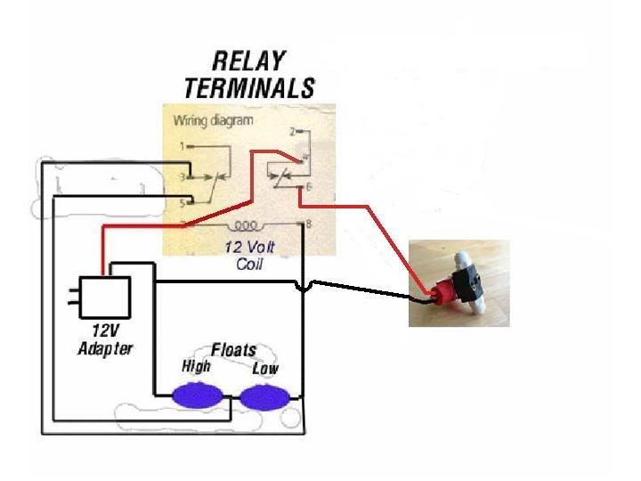 Thanks for the help!! Jay
__________________
"Opportunity is missed by most people because it is dressed in overalls and looks like work" - Thomas Alva Edison |
|
#19
12/29/2006, 11:06 PM
|
|||
|
|||
|
I went with a 12VDC solenoid. I posted my twist on the concept here. Scroll down a few posts for the pics showing the electrical progression.
http://archive.reefcentral.com/forum...hreadid=925914 |
|
#20
12/29/2006, 11:33 PM
|
|||
|
|||
|
Quote:
If you will be using a 12 V solenoid you can use a single adapter just need to insure that it has the capacity to actuate both the relay (which takes 130 to 150 ma) and the solenoid valve (which takes 500 to 600 ma) so if a single adapter is used I would recommend one with a capacity for 1000 ma (1 amp) at 12 VDC.
__________________
Did I write what I wrote? What the heck am I talking about! Well..... Nevermind. |
|
#21
12/29/2006, 11:55 PM
|
|||
|
|||
|
how your set up running brackish dude.
i am currently seting up a system that has 5 dc valves ive got the valve manifold set up and all threads cut. need to work out the circuit. anyways its going like this. they are all nc valves 1. main shut off valve to ro/di on to manifold 2. valve to main tank 3. valve to s/w change tank 4. q/t tank EDIT: sitting here and realized i dont need a pressure release so im down to 4 valves may use that fifth for some thing else Last edited by douggiestyle; 12/30/2006 at 12:36 AM. |
|
#22
12/30/2006, 12:01 AM
|
|||
|
|||
|
Jdieck, brackishdude, & Doug Thanks! The cobwebs have cleared!!
 Jay
__________________
"Opportunity is missed by most people because it is dressed in overalls and looks like work" - Thomas Alva Edison |
|
#23
12/30/2006, 12:23 AM
|
|||
|
|||
|
Quote:
OK here is what I would recommend: For Solenoid: look at mcmaster catalog 7877K5 12V dc coil 0.5 amp 1/8" FNPT 100 psi max pressure http://www.mcmaster.com/ You will need two John Guest connectors 1/8" MNPT by 1/4 tubing for it For relay I would recommend the following: From RadioShack PN 275-218 12VDC coil 10A contacts DPDT http://www.radioshack.com/product/in...entPage=family For the auto/manual you can use a spst switch or even better a momentary push button like the following: Mini SPST 0.5-Amp Momentary Switch4-Pk. Normally Open PN 275-1547 http://www.radioshack.com/product/in...entPage=search For the floats you can use: The Reef Fanatic ones if to be used in an RO/DI reservoir http://www.premiumaquatics.com/Merch...ry_Code=Dosers This float has a plug in connector like the one used for earphones so you may need to get the femeale plug ins from radio shack or cut the connector and wire them directly. or these with snail gards if to be used in the sump http://autotopoff.com/products/DT1/index.htm For a single power supply this will do: 12V/1000mA AC-to-DC Power Adapter Radio Shack PN 273-1776 http://www.radioshack.com/product/in...entPage=family For lights you can use 12V LEDS Red for activated and green for cirsuit powred. Radio shack Part Numbers 276-270 (Red) 276-271 (Green) http://www.radioshack.com/product/in...ductId=2062568 http://www.radioshack.com/product/in...ductId=2062569 I'll re-draw the circuit for a single power adapter and post it later.
__________________
Did I write what I wrote? What the heck am I talking about! Well..... Nevermind. Last edited by jdieck; 12/30/2006 at 12:38 AM. |
|
#24
12/30/2006, 12:40 AM
|
|||
|
|||
|
Quote:
Jay
__________________
"Opportunity is missed by most people because it is dressed in overalls and looks like work" - Thomas Alva Edison |
|
#25
12/30/2006, 12:43 AM
|
|||
|
|||
|
Try to enclose the float inside a piece of PVC to keep the water disturbances down. The floats should have a built in hysteresis so I don't think it's necessary to add a second float for that purpose. In my 125gal I get a few hours before float triggers and I evaporate 3 gal/day
Instead I would like to see the 2nd float used as a backup float in case the main one shorts. Also you guys need to put clamping diodes/zeners across the coils or you'll have the float fail prematurely!!!! |
|
|


 Linear Mode

