|
|
|
#51
 07/23/2005, 11:25 AM
|
|||
|
|||
|
Quote:
One inch should be fine depending on how much flow you want to put through it. If it's a sump or a sump/refugium, I would only try to have anywhere from 3-5 times tank turnover. And if you need more flow, just build another one! I recommend using a closed loop for a majority of your flow requirements. I say this because its just flow going through it, nothing more. One key point here is you really want to minimize the backpressure going to your sump to maximize the flow. With my setup I have a lot of elbows that really cut down on how much water I can process at the moment. The optimum thing would be to go straight down from the overflow to the sump with 0 bends and turns. |
|
#52
07/23/2005, 11:27 AM
|
|||
|
|||
|
Quote:
|
|
#53
07/23/2005, 11:37 AM
|
|||
|
|||
|
Quote:
Ok, I'd say no more than 50gph is all you should be putting through your sump/refugium below the 5G. 1/2" throughout will easily process that much water. And the intake/overflow doesn't have to be far under the water in your tank. I know it may be hard to find a return pump that will meet that almost exactly, but rate your pump for how much head you'll have at the top. Again you'll probably be using 1/2" vinyl tubing and 1/2" pipe. You may also want to put in a small powerhead for additional flow inside the 5G. 100-150gph PH and 50gph overflow = 150-200gph / 5G = 30-40X turnover. I'd say that is almost PERFECT. Although only a 5G, it will give good flow characteristics very well, especially if you use a "spray"-like bar on the return. I may come back to you for additional recommendations and hopefully a paint picture of how I would do it. What size sump/refugium below were you planning? |
|
#54
07/23/2005, 01:23 PM
|
|||
|
|||
|
Quote:
Quote:
 My conclusion on what size to make it out of is the deeper you can get the intake inside the tank, the more water you'll be able to process on the exit side of the overflow. This is because the exit has "a lot of water above it". But you must have the exit tee in the proper position or you'll lose prime if the power goes off. Here's a paint picture illustrating what I mean. Notice that the exit tee in all of my pictures is always above the intake elbow. This is basically all you need to remember on making these. Everything else is how you think it should go.  As for exact lengths, there's really no set length. Since it's on a 10G, I used lengths appropriate to the size of the tank. Here they are in order from the intake to the exit ball valve: 1x small piece of gutter guard siliconed to the top as a "grate" 1x1.5"ID slip coupling around 2.75" long 1.5"ID piece of PVC 2-3" in length to connect the two couplings 1x1.5"ID slip coupling around 2.75" long 1.5"ID to 0.5"ID reducer bushing into the bottom coupling 2x0.5"ID street elbows connected together and one male end in the reducer bushing 1x0.5"ID piece of PVC 7" in length 2x0.5"ID street elbows connected together 1x0.5"ID slip coupling (you can use 1 street elbow and 1 normal elbow instead of 2 street elbows and 1 slip coupling) 1x0.5"ID piece of PVC 9" in length 1x0.5"ID slip elbow 1x0.5"ID piece of PVC 2" in length 1x0.5"ID slip elbow 1x0.5"ID piece of PVC 3" in length 1x0.5"ID slip tee 1x0.5"ID piece of PVC 9.5" in length (standpipe) 1x0.5"ID piece of PVC 3" in length 1x0.5"ID slip ball valve If you've any more questions, please ask. - WarEagle |
|
#55
07/23/2005, 01:28 PM
|
|||
|
|||
|
Quote:
And no problem with modifying the pictures, if anyone would like to modify any pictures that I've posted, please feel free to download them and do so. I've no problem with it. With DIY, it's always much easier to understand something if there's a picture to look at. |
|
#56
07/23/2005, 02:11 PM
|
|||
|
|||
|
daddypugg, can you post a picture of your setup?
__________________
Make your work proud to have your name on it. |
|
#57
07/23/2005, 02:28 PM
|
|||
|
|||
|
I am going to be using a 10 gal as a sump/refugium.
I will go and buy the parts today. If you could give me the specs of how you would build it, that would be great. I will also start searching for a pump. Thanks, Chris Quote:
|
|
#58
07/23/2005, 03:30 PM
|
|||
|
|||
|
How does this design compare with the one designed by "tboned", the "$15 PVC Overflow" design? I looking to do a PVC type overflow and want to know what are the pros, cons for the ones suggested by various do-it-yourselfers? I like the dual type designed by tboned but had some questions.
What is the noise level of these PVC overflows compare to the comerical boxes? Should these overflows be turned off when feeding? I will probably have more questions when I actually start making one - I haven't even finished making the sump/fuge yet. Thanks for all the great ideas out there and for sharing with not so great thinkers like me. |
|
#59
07/23/2005, 10:05 PM
|
|||
|
|||
|
Quote:
 If you find his more indepth and easier to produce, please be my guest. It's no contest here on RC, I'm just trying to help and share some of the things that work for me. - WarEagle |
|
#60
07/23/2005, 10:12 PM
|
|||
|
|||
|
Quote:
And checking out pumps, I saw that a Magdrive 2 pumps 250 gph at zero head and reduces to 175-125 gph between 3 and 4 feet of head. You might want to look into one of those for your return with a ball valve to control the flow how you want. I typically look for pumps on Marine Depot because they usually have good specs and tables for most/all of the pumps they sell. - WarEagle |
|
#61
07/23/2005, 10:18 PM
|
|||
|
|||
|
Quote:
here ya go... 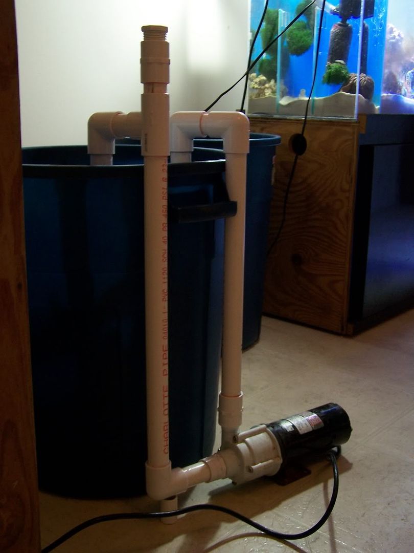 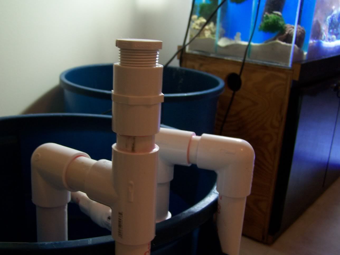 When I make up water, I just unscrew that top plug and fill with water, and everything is primed. The same principle should work for your overflow, as long as you close the ball valve until the pipe is "back" filled. |
|
#62
07/24/2005, 12:20 AM
|
|||
|
|||
|
I keep seeing comments everywhere about overflow after power outage. I understand the concern and the desire to have the overflow self start upon power comming back, but what about the GFCI breaker. Mine must be reset after a loss of power. So to get my pumps back on requires me to be there. Am I the only one?
As for the overflow, I think I will build one for my refugium to overflow into my sump. I already blew the wall out of one aquarium by trying to drill it. PVC pipe is more my skill level than drilling, and the cost of decent sized acrylic leaves me frowning. Dale |
|
#63
07/24/2005, 11:47 AM
|
|||
|
|||
|
Hi
Tinygiants if you have to reset your gfci after i power outage it should not do it .you should buy a new one.they should olny trip on a fault . like i said befor a Aqua Lifter pump will take care of you starting the overflow
__________________
Have a nice day |
|
#64
07/24/2005, 12:09 PM
|
|||
|
|||
|
I just checked, and I was wrong. I must have remembered testing of my gfci incorrectly. It does stay engaged when the power switches on and off.
|
|
#65
07/24/2005, 11:03 PM
|
|||
|
|||
|
Daddypugg, that's a different setup than the overflow. You are basically running an over-the-tank closed loop. Your pump on the floor (not sure what it is), it is providing all of the punch. If you get air in yours and as long as it doesn't make the pump become unprimed, it will pump water out of the tank and back into it regardless, kicking any air bubbles right back out.
On the gravity fed overflow, there is no pump. If you unscrew the cap on the over-the-tank section, pour in water, it will just flow out into the tank over the initial wier. Fully priming it can only be done by removing the air from the over-the-tank section. Hope I made this more clear.
__________________
Make your work proud to have your name on it. |
|
#66
07/24/2005, 11:09 PM
|
|||
|
|||
|
I was using that as a reference, the principle should be the same. If you close the valve and fill the pipe, then in essence you have trapped any remaining air (elbows over tank). thus opening the valve then would start the flow causing a suction.
I can see it clearly in my head maybe I am not explaining it correctly. |
|
#67
07/24/2005, 11:44 PM
|
|||
|
|||
|
Quote:
 Assuming the brown box is your cabinet, the 5G is on top and the 10G is below containing skimmer (D), venturi pump (C), heater (F), and return pump (G). On top is the 5G with the air pump (B) beside it (room available in cabinet, can easily put it there). Note that the heater (F) is laid in the sump depthwise in the 10G. Finding a heater this size may be difficult, but you can always turn it diagonal under the baffles, principle is the same. I'd recommend a cheap 50W submersible (titanium if you can) heater. (E) is the gate valve on the skimmer. Please read Mr. Anthony Calfo Skimmer Improvements Thread to fully utilize your skimmer (they give good recommendations there too!) to the best of its ability. You'll see why I recommend the venturi pump AND the air pump. You'll also need to put a needle valve in between B and C in the airline. Ok (A) would basically be a manifolded spray bar return. I don't have a webpage handy for this, but if you search around for spray bars in the search, you should find a lot of good ideas for these. Basically you want to produce random movement in the tank. Pressure comes in and is distributed somewhat equally throughout the tank. Throw in 1 or 2 small powerheads (Mag drive mini's work well!) and you're flow requirements are met in this small system. Hopefully I've given you some ideas to really run with. Search around first for ideas, then bounce your ideas to some of the experts (direct PMs if you have very specific questions) here on RC. Then put it all together. Good luck! |
|
#68
07/25/2005, 12:00 AM
|
|||
|
|||
|
Quote:
I just don't think it would work. In fact I'm fairly certain it wouldn't. If you put the cap on tight (no air leak), when you opened the exit ball valve the water would have to stay at the top of the stand pipe, not fall. It can't fall because it will create a vacuum at the top of the standpipe near the cap and vacuums = bad juju in physics. If you have a small hole or a leak at the cap and you open the exit ball valve, the water molecules in the standpipe will just say, "Hey why stay up here when we can go down this new little hole?" So off they go down your exit pipe to the sump. You'd want them to all grab hold of the water molecules further in the system on the other side of the tee and pull them up and out the exit tube, but instead they're like "Screw you guys we're outta here!" Nothing happens but your standpipe water exits. I just don't think there is any way you can use water to start this system. Air has to be pulled out of the somehow to prime it. Easiest way is for you to use own lungs to pull that air out. Whether you're pulling the air out the top of the loop or producing a suction on the bottom of the loop and pull the air out that way. If you pull the air out, water will stay right behind it taking over its territory and priming the system. Hopefully this illustration--sorry for the water molecule discussions--will bring about a more thorough understanding. - WarEagle |
|
#69
07/25/2005, 03:20 AM
|
|||
|
|||
|
wonder if you could make the inside of the tank plumbing out of ABS which is BLACK plastic so it would blend better with black backgrounds. you might find the size works just have to convert ABS down to 1" or whatever on the outside.
Abs come already in 1.5" sizes which is perfect for the larger piping that is inside the tank, you might even use a standard drain trap (ABS) and a BLACK DRAIN Tailpiece to bring the water up out of the tank using ALL BLACK plastic, then you just have to modify it to connect to the PVC on the outside down to the 1" |
|
#70
07/25/2005, 09:35 AM
|
|||
|
|||
|
wow a lot has gone on since i posted last. Sorry i missed some of it. Just to give you an update on playing around with 1 inch pipe. I ended up putting the t valve on the overflow portion (prior to reading the posts) to get a better start on the siphon for testing. The final results will be a hole with a check valve in order to fit under the Canopy if I use this design.
Playing around with the 1 inch pcv i found the maximum flow rate is around 330 GPH at the trap exit drain. I wasnt able to get more that this. Put that in reference to Daddypugg's pic. The outlet flow at the pump input (just flow) with out the trap portion is about 500 PGH. So the trap portion restricts flow by a hugh amount but if you were running a closed loop you would be turning more water. Test setup Overflow trap setup is 1 inch pipe Return Mag 9.5 going to a scwd using 3/4 hose at 4 ft head with a T and ball valve off the pump to control flow. Just to let you know inscreasing the output side of the pump to 1 inch will not effect the system.
__________________
"What is a scientist after all? It is a curious man looking through a keyhole, the keyhole of nature, trying to know what's going on." -Jacques Cousteau |
|
#72
07/27/2005, 11:15 PM
|
|||
|
|||
|
I built one of these bad boys today. I love the idea but I'm not getting enough flow with 3/4". Would increasing the beginning pipe diameter increase flow? Like if I increased it to 2"? Or is increasing the main pipe to 1" be the only way? Or would both help?!?
Last edited by jdmara; 07/27/2005 at 11:26 PM. |
|
#73
07/27/2005, 11:56 PM
|
|||
|
|||
|
Here is something I'm building.
It is based on the model that was posted here, but I made some changes. I did not like a look of pipes inside the tank, so I tried to make less of them visible. This is going to be in my 55 gallon tank with Mag 5 return.  The gray pipe is 2" in diameter. This is the only part that should be visible in aquarium. I'm using 1" pipe for overflow itself. Don't know what flow it will support yet. I'm waiting for my Mag 5 to test everything. I'm still thinking if I wnat to increase pipe at the very end of the way (brown staff on the picture). The fun part was to find out the way of putting 1" pipe inside 2". I found 2"x1" reducer at HomeDepot. I had to make soe cuts to make it look like a star (green element on the picture). I tried it for about 5-10 minutes. It works if you can get air out of the system. I notived that this will not be enough to support 500-600 gph flow. You, probably, will need two of them for such task. Another option would be to increase diameter of the pipes. Not sure if you want to increase 1" - there will be potentially more problems with air if you go to wide. Changing 2" pipe to go with 3" in the tank can help to increase a flow a little. Please let me know what would be the difference if you try it. Any comments on this overflow are welcome. You also can change and improve it as much as you want. Just let us know the results, so we all can do a better job
|
|
#74
07/28/2005, 09:19 AM
|
|||
|
|||
|
I changed my over the tank portion like you did. This way it was easier to suck the air out. Eventually it will need a hose and check valve to make it eaiser to work with, but for just testing stickinga small hose into the pipe to suck air works great.
I was thinking of going up to 1.5" pipe but decided to make a unit second unit and join them. Kinda like the $15 Pvc overflow. This allow for skimming from two sides of the tank and will be able to get roughly 600 Gph. I like your reducer idea. I used a cross fitting on the end of the shipon tube clused to the bottom of the skimmer portion. I cut the two horizontal peice short to fit and then glued it into a 2 in cap attcahed to the bottom. I wil have to take some pics when I get a chance.
__________________
"What is a scientist after all? It is a curious man looking through a keyhole, the keyhole of nature, trying to know what's going on." -Jacques Cousteau |
|
|


 Linear Mode

