|
|
|
#1
 01/02/2008, 10:43 AM
|
|||
|
|||
|
Adjusting tank-sump flow
I've recently set up a 120g AGA RR tank and 40g sump. The sump has three sections, inflow, return and refugium, and flow is controled by three gate valves.
I'm having a hard time balancing the flow between the tank and the sump--that is adjusting the flow so the same amount of water is flowing into and out of the sump. What's the easiest way to do this. Now I spend about an hour tweaking the inlet valve to the skimmer section. thanks, Richard |
|
#3
01/02/2008, 11:36 AM
|
|||
|
|||
|
That may be my problem.
I've got two valves on the pipes to the overflow, one controling flow into the skimmer section and the other into the refugium. The third valve is above my return pump. Right now the main drain, into my skimmer section is somewhat restricted. |
|
#5
01/02/2008, 12:43 PM
|
|||
|
|||
|
Here is my suggestion. One drain line to the skimmer section, unrestricted. The second drain tee'd with a valve restricting flow to fuge with excess running over to skimmer section. You do not have to match flow to skimmer. In the end it all gets skimmed through turnover. What size is your return pump? I had a similar setup once with a mag 12.
|
|
#6
01/02/2008, 12:56 PM
|
|||
|
|||
|
I have an Eheim 1260 (635 gph).
Right now, the two pipes from my overflows are joined with a T and then separated by a second T, one pipe going to the skimmer section (with a valve) and the other going to the refugium (with a second valve). |
|
#7
01/02/2008, 01:37 PM
|
|||
|
|||
|
Quote:
|
|
#8
01/02/2008, 02:37 PM
|
|||
|
|||
|
I'd rather not cut that valve out. Right now, it's partially closed. I'll open it all the way and see if that solves the problem.
Should it be easier to balance the sump in flow and out flow with that valve completely open and just adjusting the valve over the pump? |
|
#9
01/02/2008, 02:59 PM
|
|||
|
|||
|
I don't see why it would be difficult to balance out. Your drains shouldn't be restricted. Your drains should be allowed to drain to the skimmer and fuge. Now you should restrict how much flows to the fuge section, but the rest goes to the intake section. Then you use your ball valve to restrict flow on the return to match up with your drains. Your return pump should never run wide open. It should run 70-80% if possible.
__________________
Frank |
|
#10
01/02/2008, 03:14 PM
|
|||
|
|||
|
i'm thoroughly confused now....lol maybe i didn't read it right but why cant you restrict your drains?... id rather restrict my drains then put additional pressure on pumps that aren't made to handle pressure
if your drains are too small for the pump/s thats a different ballgame in which you just need a diverter (t) back to the refuge. put a ball or gate on the refuge return only (this will reduce the work your pump has to preform. )
__________________
Thanks Clear Fabrications! (Seattle) |
|
#11
01/02/2008, 03:18 PM
|
|||
|
|||
|
if you look closely i also have 3 valves (different sump setup)
2 valve restgict the amount of (maintank flow) and another restrictes and controls the flow to and through the refuge... 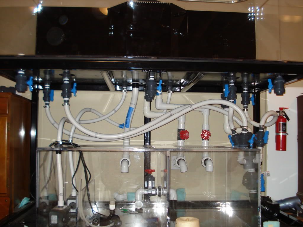
__________________
Thanks Clear Fabrications! (Seattle) |
|
#13
01/02/2008, 04:27 PM
|
|||
|
|||
|
You guys are making this too complicated. This is a common mistake of sump and plumbing design.
The size of your return pump decides the total flow going through the system. Let's say you have a return pump that when wide open pushes 1000gph. You must design a drain that can handle at least 1000gph, but typically should be able to drain 1 1/2 times the rated amount. Therefore, you should have a drain that can handle 1500gph. So, let's say your drain can handle 1500gph. Then with 1000gph running through the system there will be no mismatch problem, regardless of what you do with the fuge, because the fuge flow is coming from the same drain line via a Tee. Therefore, you are only controlling the flow leading to the fuge and it will not affect the total amount of flow coming from the drain itself. Now, if you choke back the return pump to 500gph, then you still will not have an issue with mismatch because the drain will easily handle this lower flow, thus you will only observe less flow and less noise when draining. Drains should never be restricted during normal operation. Doing so is a newbie mistake of which I was guilty of on my first system design. Installing a valve on the drain is fine, but it should only be used for maintenace reasons. Likewise, return pumps should only be restricted if the flow return to the main display is too large (but that would lend to a poor pump choice). Head pressure resulting from plumbing the return line puts enough backpressure on the pump that one should not have to restrict it any further. With that in mind, your problem is a result from restricting the drain. This may be occuring from one or two flaws in teh design. One, you are choking off the flow. Which you defineatle are, so open that valve and leave it wide open. You can do anything you want to the fuge valve, that is fine it won't effect the handling capacity of the drain since clsing it completely will just force teh water to go down the other line and into the sump. Two, with a wide open valve on the drain, your drain pipe itself is two small to drain the volume of flow being pushed into your tank. Therefore, the drain itself it not able to handle the flow from your return pump. This becomes a simple fix. You must choke down the return pump to be less than the capacity of the drain. Or, rebuild a drain with a larger PVC pipe (assuming you are using some sort of internal drain). You did not reveal photos or specify if you are using an overflow box or an internal drain with Durso pipe, or whatever. That info would help to diagnose the problem.
__________________
Cheers, Scott |
|
#15
01/02/2008, 05:37 PM
|
|||
|
|||
|
Drains should never be restricted during normal operation. Doing so is a newbie mistake of which I was guilty of on my first system design.
help me out... why? are there extenuating circumstances? my return pumps push 1800 gph yet 2x 1.5" drains can drain over 3000gph so why cant I restrict the drains to meet the needs of the pump. it is not beneficial to push over 3000gph through a sump. this is the way my tank has been designed -- no mistakes -- i have the ability to push more but not the need.
__________________
Thanks Clear Fabrications! (Seattle) |
|
#16
01/02/2008, 06:06 PM
|
|||
|
|||
|
DO NOT RESTRICT DRAIN LINES. It is that simple. If you pump 1000 gph a 3000 gph drain will drain 1000 gph. Now if you restrict the drain to 1000 gph and algea grows (it does that), or a snail crawls, your drain now won't handle the 1000 gph and a flood occurs.
A drain will only drain what is pumped up to it. oversize and unrestrict the drain and control the pump. |
|
#17
01/02/2008, 06:22 PM
|
|||
|
|||
|
Overflows should not be restricted. The flow will balance itself according tothe flow of the return pump. The level in the display tank and over the overflow weirs will establish itself according to this flow. No adjustment is needed unless you return pump is too large in which case you valve down the discharge or return side of the pump only.
|
|
#18
01/02/2008, 06:31 PM
|
|||
|
|||
|
Ret25yo, you have a complicated system.
It looks like you have two drains with valves on the right side. Is this the fuge? The other drain appears not to have a valve and it drains unrestricted right into the center of the sump. Is this correct? Using valves in your case is valid because you are attempting to limit the flow into the fuge chamber. However, the unrestricted drain into the center chamber is draining the rest of the flow and should be unrestricted as you are doing it. Here is the concept I am trying to demonstrate: You don't need to restrict the drains to meet the needs of the pump, because the pump itself limits the ability of the drain. Your pumps push 1800gph. Your drains are capable of draining 3000gph unristricted. The total flow through your drains is still only 1800gph. That leaves a balance of 1200gph capacity to drain more water. BUT you don't need it. So, let's say you restrict your drains down to 2000gph. It still does not change the flow through the system of 1800gph. So even though you think you are meeting the needs of your pump, it does not matter until you over-restrict. You can set your drains to drain anywhere from 1801 to 3000gph, and nothing will appear to be any different. Now, let's say you over adjust and you turn your drain capacity down to 1600gph. You will now observe similar problems as Riclat. The drains will not keep up to the flow in the tank and the water will back up in the drain pipes and flood the overflow reservoirs and essentially the maintank. So this is the rationale for not restricting drains. It is totally unecessary to place a valve on the drain since it will only drain the amount of water pushed into the tank by your return pump. What I see happening in your system is that you are restricting flow into the fuge so that it is slow. Let's say that those two drains drain 400 gph. That means the other drain is draining 1400 gph. If it only has teh capacity to drain 1500 gph then you only have 100gph of head room. If you were to increase your main system flow to 2000gph then you would see a problem. Again, all this information is hypothetical because we do not actually measure any of these flow rates, we just estimate them. But if Riclat were to measure the actual flow rates of his return pump, I will promise you that it pushes out more water than measured by the drain. In other words, the more head room you have as a result of the drains collective capacity, the safer your system will be. Hope this makes more sense.
__________________
Cheers, Scott |
|
#19
01/02/2008, 06:32 PM
|
|||
|
|||
|
Maybe this will help ...
Assuming that your drain or drains are large enough, they will always drain the exact amount of water per hour (or minute or ...) that your return pump is pushing back to the tank. You can have a 10" drain line and a 1000 GPH pump, the drain line will only drain 1000 GPH wide open, no valve needed. It would be a different story if the opening to the 10" drain was 1/2 way down into the tank in which case it would form a siphon that would siphon faster than the 1000 GPH pump could pump water back to the tank. But it is an overflow, not a siphon. Only the water that the pump pumps back to the tank will overflow and that will only happen at the rate that the pump can push the water back to the tank, regardless of the drain size (as long as the drain is large enough to handle the pumps flow). |
|
#21
01/02/2008, 06:36 PM
|
|||
|
|||
|
Holy Cow Scott! Makes my fingers tired just reading it!
|
|
#22
01/02/2008, 07:02 PM
|
|||
|
|||
|
scott... dont let the setup pictures fool you.. those two valved drains are my MAIN drains(1.5") the other unrestricted is simply a backup drain to keep my tank from overflowing in case i do "overrestrict" the main drains...lol
the valve on the bottom back of the sump actually controls the fuge flow as the main drains are in a separate "compartment" point is: #1 my main drains are restricted as I only want 1800gph(main return pumps) processed through my sump at a time #2. i have the ability to fully (unrestrict) my main drains, if I wanted more processed and if i had bigger pumps pushing the water back up. #3. if I had only ONE 1.5 drain and 2 800gph returns I would add a T to the (return plumbing with ball valve) to equalize the level and relieve any direct pressure i would be placing on the tank with a in-line ball or gate valve. now my fingers hurt.
__________________
Thanks Clear Fabrications! (Seattle) |
|
#23
01/02/2008, 07:10 PM
|
|||
|
|||
|
Even with the valves in the fully open position its only going to flow 1800 GPH or whatever the pump is rated at at that head. It will establish its own height in the display tank accordingly, you don't need to do anything.
The overflow will regulate itself according the the height of the water in relation to the teeth on the overflow box. It would be different if your overflows were not at the top of the tank, then your level would bee too low in the display. |
|
#25
01/02/2008, 07:35 PM
|
|||
|
|||
|
So is mine but my return extends down into the very bottom of the main sump area using a long sweep so it does not crash down. Any noise is controlled by the addition of air into the overflow water using a modified Stockman Standpipe. Totally silent.
|
|
|


 Linear Mode

