|
|
|
#1
 10/01/2007, 10:41 AM
|
|||
|
|||
|
Return manifold
Wondering if someone would cast an eye over this design and tell me where I might encounter any problems (if any?)
 Im running it off a Aqua Medic OR6500 One of the exits on the bypass is for a Phosphate reactor and the other as a spair. |
|
#2
10/01/2007, 03:50 PM
|
|||
|
|||
|
*BUMP*
ANYONE? |
|
#3
10/01/2007, 07:23 PM
|
|||
|
|||
|
A union directly above the pump would be a decent addition, wish I had done that to my return. Additional unions on the return manifold up top would be nice but certainly aren't needed.
You may want to change the section above the first T to flexible PVC to reduce some vibrational noise and stress (and possibly eliminate a 90/Elbow). Remember to drill a siphon-break hole or two on the return "nozzles", if they will be submerged at all. Cheers, Marty |
|
#7
10/02/2007, 02:27 AM
|
|||
|
|||
|
Hi thanks for the input,
FishInMN > took the advise and put in a union after the pump. Cant do Flex because in UK its all in imperial measurements starting a 2 and is 3 times the price of the metric stuff sold in the fish shop. To counter this I have changed the 90 elbow for a swept one. Frazier> Where about do you mean? Up the top? Chrisjet> Yep sorry to throw you there all fittings are it metric. Can get imperial stuff but cant get tank connectors and the fittings are 3 times the price. Have to get them from a swimming pool supplier. 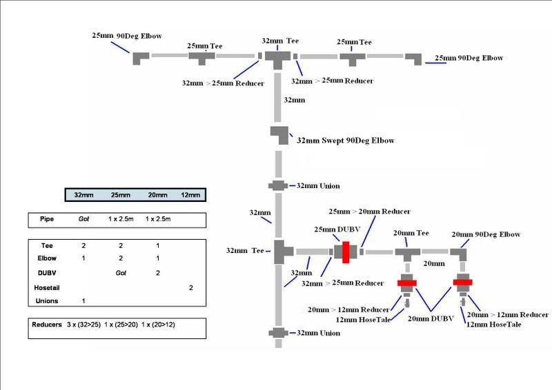
|
|
#8
10/02/2007, 10:53 AM
|
|||
|
|||
|
I'm pretty sure the experts would suggest you set up the 'Ts' differently, including Sprung vol 3. When you branch flow with a 'T' i believe it's best, if possible, to run the flow into one of the branches of the 'T' not from the stem, if that makes sense. Otherwise you're forcing flow into a dead end, which adds much resistance. Apparently easier to give the flow option of either straight ahead or right/left turn than hitting a dead end and then either going right or left. The flow of the 'T' in the preferred setup is then balanced by a ball or gate valve on each output after the 'T' to balance flow according to need.
|
|
#9
10/02/2007, 11:02 AM
|
|||
|
|||
|
Tylorarm>
How would this work? I have the 90 swept over the tank rimm then a lengh to the front of the tank the Tee of the the left and right. Can see how I would do it the way you describe coudl you elaborate please? |
|
#10
10/02/2007, 11:27 AM
|
|||
|
|||
|
I don't know how to attach a drawing, but the concept is that if you look at the "T" in quotes, the input of flow should be either in the top right of the "T", or the top left. If you use the bottom of the "T" as the input of flow the flow hits a dead end and slows substantially. Just imagine the flow going into one of the three possible input places of a "T" shape then imagine its path forward. However, I'm not sure given space constraints ect. if you are able to rearrange your plumbing to optimize flow resistance in this way.
|
|
#12
10/02/2007, 11:38 AM
|
|||
|
|||
|
Ok, after reading this again i see that the pump is at the very bottom of the chart (you added a union after the pump). Thus, the first "T" is set up best for flow and the second one (at the top of the chart) is not. Not sure if you can change it or not, but food for thought. Also, you might want to consider making the second union from bottom to top a union ball valve, just in case you're not getting enough flow to turn right but probably not necessary.
|
|
#13
10/03/2007, 02:13 AM
|
|||
|
|||
|
Oh! I see now. the space constraints are tight up the top so the last T at the top of the riser might hav to stay like that. I have a spair DUBV so I can swap the union over to one but as you has said and I have through I might not need it. This branch is to feed equipment and so the flow rate can't be to great because its a fluidized PO reactor and a calcium reactor.
Many Thanks for the input tho tylorarm. On a differant note do you think the pipe sizes are ok? |
|
#14
10/03/2007, 09:02 AM
|
|||
|
|||
|
Another suggestion: I usually put a union and a ball valve on either side of all my pumps. This allows me to swap out/service the pumps with only the water inside the pump spilling out (less than a cup of water usually).
__________________
"With great power comes great responsibility" - Uncle Ben |
|
#15
10/03/2007, 09:44 AM
|
|||
|
|||
|
Nice. all the Ball valves I'm using are doble union ball valves so I think I'm ok.
|
|
#16
10/03/2007, 09:59 AM
|
|||
|
|||
|
Sorry that reads a bit rude>
Thanks for the input. Still wondering about the pipe sizes |
|
#17
10/03/2007, 03:15 PM
|
|||
|
|||
|
Well, 25mm and 32mm are about 1in and 1.25in pipe, respectively. Assuming you're going to get 4000lph (~1050gph) from the OR6500 after the split and with head loss, your pipe-size selection is good. The flow from each "nozzle" up top will not be noticeably strong.
What sort of drains do you have on your setup? I'm assuming the 48x18x18 listed in your signature is the tank in question, so assuming you do get about 4000lph from the return, you will need at minimum a 1.5 inch (38mm) drain to keep up. Two, one-inch (25mm) drains would also suffice... Just curious. Cheers, Marty |
|
#18
10/03/2007, 03:53 PM
|
|||
|
|||
|
I have 2 x 32mm drains. and yes the tank is the 48x18x18 in the sig. Not the actual tank but one the same to replace because in a recent tank move I cracked it.
Thanks for the input. Just need to get on with it now. Thanks again. |
|
|


 Linear Mode

