|
|
|
#1
 07/17/2007, 01:17 PM
|
|||
|
|||
|
Can someone help me build this DIY GFCI powerstrip?
In reference to my thread here I think my best solution is to build a DIY powerstrip. The ones I can buy just aren't working, so I want to make a quality one with leviton outlets. Anyway, I want to make something similar to this:
 But I have no idea how to wire it, I've never done this before. I really don't want to burn the place down, so I'd appreciate some help. I'd like mine slightly different from the picture though. I was thinking of two GFCI outlets in the box instead of one and regular outlet. I've heard that if I wire the GFCI's in parallel they will operate independently of each other. That way I can have the lights on one, and the pumps on the other. So I guess my question is, what do I need, and how do I wire a box like one pictured above, but with two GFCI's in parallel? Thanks |
|
#2
07/17/2007, 01:38 PM
|
|||
|
|||
|
if you want to run in parallel you will need to have two cords coming off of the box. if you run in series then one GFCI and one cord is all you need but both are protected by the GFCI so there is no need to two really. unless you want to waste money.
just buy the box and the GFCI, one regular outlet...a faceplate... and i think they even have replacement cord you can buy. lowes has all the pieces parts in one isle.....very easy... it's like playing connect the dots with something that can kill you.... |
|
#3
07/17/2007, 01:42 PM
|
|||
|
|||
|
I don't want two outlets protected by one GFCI. I'd rather have two separate GFCI's so that I can have different components on different GFCI's. So that say if the lights someone trip the GFCI they don't take the pumps down with it. I'd want at minimum my two circulation pumps on their own GFCI. I saw in another old thread a guy that did it with one cord and multiple GFCI's, but I'm not sure how.
|
|
#5
07/17/2007, 03:26 PM
|
|||
|
|||
|
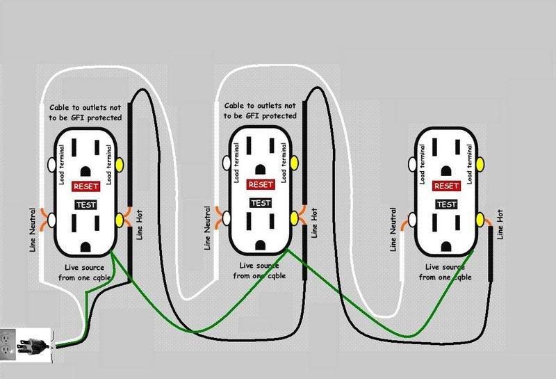
Look at this picture and where the initial load comes in just daisy to the next one. That way you have one plug to the wall but separate protected outlets.

__________________
If my phaser discharges off by as little as .06 terra watts, it would cause a cascading exothermal inversion. Last edited by cannarella; 07/17/2007 at 03:32 PM. |
|
#6
07/17/2007, 04:46 PM
|
|||
|
|||
|
So say I wanted two GFCI's like above. I come off the cord from the wall to the Line neutral and line hot on the first outlet, and then run another line from the line neutral of GFCI 1 to the line neutral of GFCI 2, and also from Line hot of GFCI 1 to line hot of GFCI 2. If all I want is those two outlets, that's all that needs to be done, no wires are coming off GFCI 2 (unless I wanted yet another outlet) at all, correct?
|
|
#7
07/17/2007, 05:07 PM
|
|||
|
|||
|
Its really simple. If you have two GFCI outlets, connect all the black terminals/wires together, all the white terminals/wires together, and all the ground terminals/wires together. This is exactly the same as if you were wiring two standard outlets to the same circuit.
__________________
"Knowledge is what you get when you read the directions, experience is what you get when you don't." - Unknown Yes, I really do design rockets for a living. |
|
#8
07/17/2007, 05:13 PM
|
|||
|
|||
|
Quote:

|
|
#9
07/17/2007, 05:21 PM
|
|||
|
|||
|
You only need one GFI per circuit. Just have it at the front of the circuit, where the power comes in. If it trips it will kill power to everything.
Also for wiring remember white to bright (silver) and black goes to gold. This is same on all 115-120 VAC home outlets and switches. I was told this years ago by a journeymen and I sitll hear people saying it.
__________________
Honey, can I have a bigger one please? This is the last time I will upsize, I promise! |
|
#10
07/17/2007, 06:26 PM
|
|||
|
|||
|
Quote:
You certainly do NOT need two cords. GFCIs can be wired in parallel on the same circuit. you CAN NOT run GFCIs in series. Very strange things happen. It is certainly a great idea (not a waste of money) to utilize more than one GFCI on a single branch circuit. You can isolate critical equipment on seperate GFCIs. That way if one piece of equipment faults or there is a nuisance trip, all of the OTHER equipment continiues to run. |
|
#11
07/17/2007, 06:28 PM
|
|||
|
|||
|
Quote:
 Not that you can ALSO connect outlets to the load terminals of the individual GFCI receptacles. They (the downstream receptacles) would be protected by THAT GFCI. Shoulda read further before I responded the first time! |
|
#12
07/17/2007, 06:29 PM
|
|||
|
|||
|
Quote:
We want critical equipment isolated so that it DOES NOT turn off if there is a problem somewhere else in the tank (or a nuisance trip). |
|
#13
07/17/2007, 07:23 PM
|
|||
|
|||
|
Thanks Bean for keeping me in check. I crawled out from under another rock...
__________________
If my phaser discharges off by as little as .06 terra watts, it would cause a cascading exothermal inversion. |
|
#14
07/17/2007, 09:00 PM
|
|||
|
|||
|
So I went to Lowe's and started gathering stuff for this box, and then wussied out and bought a different plug-in GFCI
 Anyway, that one of course trips as well. But I noticed that if I plug each bank of lights from my fixture (the TX5 has two cords, one controls 2 lamps, and the other 3 lamps and the fan) into a separate GFCI, it works fine. I may just do that, because I don't know if I'm entirely comfortable building this DIY GFCI powerstrip since I've NEVER done any electrical work. Anyway, that one of course trips as well. But I noticed that if I plug each bank of lights from my fixture (the TX5 has two cords, one controls 2 lamps, and the other 3 lamps and the fan) into a separate GFCI, it works fine. I may just do that, because I don't know if I'm entirely comfortable building this DIY GFCI powerstrip since I've NEVER done any electrical work.If I do decide to build this box, does this look like the stuff I'd need? 2 GFCI outlets 1 Plastic outlet box 1 Face plate 1 6 foot length of 12 gauge powercord 1 3-prong plug Some length of 12 gauge wire for wiring between the outlets (should I get solid or stranded?) I would then wire the black (hot) from the incoming power cable to GFCI 1 and the white (neutral) wire from the incoming power cable to GFCI 1, and the green (ground) wire from the power cable to GFCI 1. Then I take a length of the 12 gauge wire and go from the hot line of GFCI 1 to the hot line of GFCI 2, and then another length of wire from the neutral line of GFCI 1 to neutral line of GFCI 2. Am I right so far? Then do I need to wire from the ground of GFCI 1 to the ground of GFCI 2? Not sure what to do with the ground wire. I found all the stuff I needed at Lowe's except for something to put on the input of the box to protect the power cord. All they had was these metal ones that had two screws that would seal a plate down on the cord. I was looking for the round one like in the picture. |
|
#15
07/17/2007, 09:36 PM
|
|||
|
|||
|
For the power cord I would buy a replacement appliance cord or an extension cord and chop off what you want. Defiantly go with stranded.
I would use solid wire to the individual GFCI. Use the quick connect terminals on the back. Strip the solid wire according to the diagram on the back of the GFCI. The ground you'll have to use the screw terminals. You'll end up with 3 wires coming off both GFCIs. Then just wire cap the hots, neutrals, and grounds together to the power cord coming in.
__________________
The Reptile File Forum (Google It) Discussion forum dedicated to geckos, lizards, snakes, turtles, amphibians, and other reptiles. |
|
#16
07/17/2007, 10:03 PM
|
|||
|
|||
|
Yes that is what you need. I would go with the appliance cord like he ^ said. Just make sure that it is minimum 14 awg for a 15 amp circuit or 12 for a 20 amp circuit. When you open the GFCI outlets there will be a sicker over one set of screws. That is the "load" terminal identified above. Do not use those. You want to just use the terminals marked "line" You also want to link the ground between the 2. On the back of the outlet does it look like below or are there holes where you stick in the wires and the screw clamps down on them? This can help us help you out on the easiest and best connection method

__________________
If my phaser discharges off by as little as .06 terra watts, it would cause a cascading exothermal inversion. |
|
#17
07/17/2007, 10:51 PM
|
|||
|
|||
|
OK, forgive my (extremelly) crude drawing, but is this about it? The triangles are screw wire caps BTW. Red is hot, yellow is neutral, green is, of course, ground.
 I was thinking of the already wired cored, but the smallest I could find in 12 gauge was 15 feet, a little pricey. If 14 gauge is fine for 15 amps, I'll just grab one of those, I found a 6 footer. |
|
#19
07/18/2007, 07:33 AM
|
|||
|
|||
|
Either of those diagrams is correct. Its just personal preference of whether to wire cap or just run them down the line.
When using the screw terminals make sure to wrap the wire clockwise around. You tighten screws clockwise and it will pull the wire in and not try to push it out of the screw terminal. In the last diagram make the cord coming in long enough to go to both outlets. Strip a small section off the insulation off a couple inches from the end of t wire wrap it around the screw terminal, then strip the end of the wire and do the last outlet.
__________________
The Reptile File Forum (Google It) Discussion forum dedicated to geckos, lizards, snakes, turtles, amphibians, and other reptiles. |
|
#20
07/18/2007, 07:51 AM
|
|||
|
|||
|
I like your first diagram better with the pigtails. That is how I would do it. With screw connectors it is very difficult to get 2 wires on them. The coneection would not be very tight. I don't even know if it is made to do that. I would stick with plan A. Just make sure the wire nuts are tight and you will be good to go.
__________________
If my phaser discharges off by as little as .06 terra watts, it would cause a cascading exothermal inversion. |
|
#21
07/18/2007, 07:55 AM
|
|||
|
|||
|
Thats why I said if he wants to do the screw terminals you need to make the power wire coming in long enough to go to both outlets. You strip a section a 6 inches from the end about an inch long and wrap it completely around the screw terminal. That way you have a solid connection with one wire. The end of the wire then goes to the last outlet.
__________________
The Reptile File Forum (Google It) Discussion forum dedicated to geckos, lizards, snakes, turtles, amphibians, and other reptiles. |
|
#22
07/18/2007, 08:10 AM
|
|||
|
|||
|
You can only have 1 wire per screw terminal. The new code (I if I remember) will also require pigtails instead of using TWO screws to pass the power through the receptacle.
|
|
#23
07/18/2007, 08:19 AM
|
|||
|
|||
|
That's what I was thinking but I was just using common sense instead of code...
__________________
If my phaser discharges off by as little as .06 terra watts, it would cause a cascading exothermal inversion. |
|
#24
07/18/2007, 08:23 AM
|
|||
|
|||
|
Yeah... trying to jam two wires onto one screw terminal never works too well does it. Kinda like trying to date two girsl at one time... never works out too wall.
|
|
#25
07/18/2007, 08:30 AM
|
|||
|
|||
|
Quote:

|
|
|


 Linear Mode

