|
|
|
#1
 09/04/2007, 12:12 AM
|
|||
|
|||
|
This thread was automatically split due to performance issues. You can find the rest of the thread here: http://archive.reefcentral.com/forum...4#post10696784
|
|
#2
09/04/2007, 12:12 AM
|
|||
|
|||
|
Jonathan: It may but probably not at their full potential. Keep in mind that Penductors have a 3/8" orifice. That creates a huge amount of back pressure that will make any pump with little head or pressure capabilities look like a cheap powerhead.
 I run an Iwaki 55 on each Penductor. Here's some good reference material when deciding on a capable pump... I run an Iwaki 55 on each Penductor. Here's some good reference material when deciding on a capable pump...http://www.kthsales.com/website/Misc...nthusiasts.htm Joseph. |
|
#5
09/04/2007, 12:50 PM
|
|||
|
|||
|
i don't know what caused it to bind/clump up like brick? my PH has always been on the low side (7.9-8.1). alk 9-11dkh, ca 425-450, mg 1350-1425. i think it might have been the actual type of sand itself. when i had southdown many years ago, it didn't bind up.
anyways, enuf about my woes. your tank continues to amaze me! i need to get a frag of that northstar multi that steve distributed to a couple of ya .
|
|
#6
09/04/2007, 03:51 PM
|
|||
|
|||
|
RGibson: I use Salifert test kits.
tfp: Thanks and the Northstar is still growing out but you are welcome to a frag. As to the sand, you may be correct in that it is based on granule size. That, and the pesky glycocalyx excretions ...http://www.ronshimek.com/Deep%20Sand%20Beds.htm Do you by chance run vinegar in your Kalk-reactor?... http://www.aquariumfish.com/aquarium...id=124&search= Whatever the case, Southdown is my sand of choice and I've never seen a hint of clumping since using it. And it remains very white for excellent reflective properties. Joseph. |
|
#8
09/04/2007, 05:46 PM
|
|||
|
|||
|
Quote:
"55RT - ( 1/9 HP) - definitely you would really charge one - you might what to distribute the wealth and use two." Do you think a 55 could power two of them?
__________________
Rich Durso Visit My Chunk of the Ocean, click the Red House above. |
|
#10
09/08/2007, 12:56 AM
|
|||
|
|||
|
I'm sure a single 55 could run two Penductors but in my application, I opted to run one each. The reason being is that I have one on each end of the 8' tank that needs to send the stream of water as far across this length as possible. My thought was that if I added a second (2 firing L to R and visa-versa), it may move slightly more overall water but I would lose the velocity required to travel such a relatively long distance.
For reference, here's the top view diagram. Albeit prior to those pesky corals filling in all that light blue, open-water depicted area. 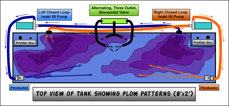 Joseph. |
|
#11
09/08/2007, 11:39 AM
|
|||
|
|||
|
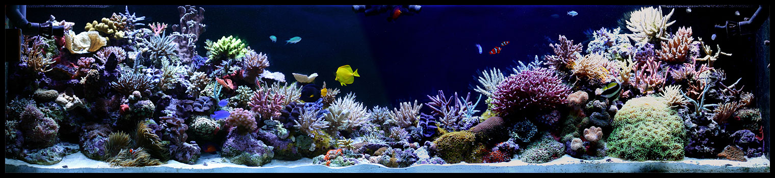
Since this is now the third split section on this thread and its grown larger than I ever would have expected, heres a quick visual recap with relatively brief text descriptions. Hopefully, this will help answer questions for those new to this thread and my 240-gallon (8x2x2), dual prefilter, Oceanic in-wall tank build. Here we go
again.
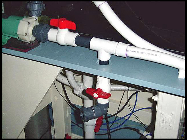
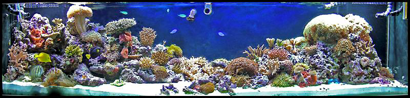
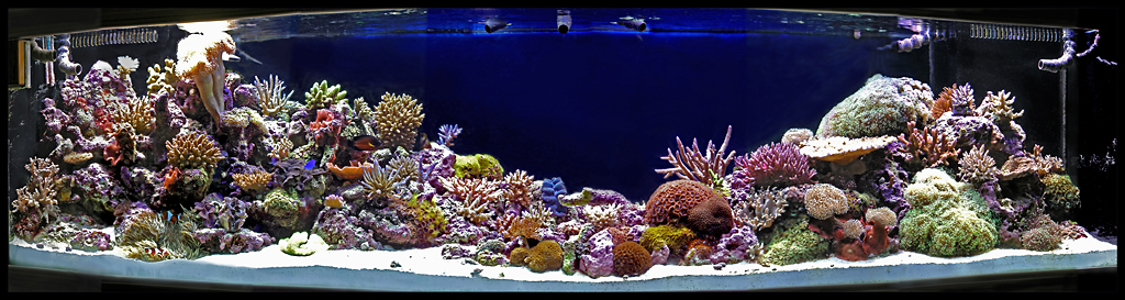
This tank was an upgrade from my previous 65-gallon tank and was years in the thinking stage. I started the deconstruction of the bedroom that is adjacent to our living room in August of 2003. Water went in September of 2003 so the tank is celebrating its 4-year anniversary. To show you were we are today (or at least a few days ago), heres a full tank shot followed by the three separate images that made it up to start the image documentation series 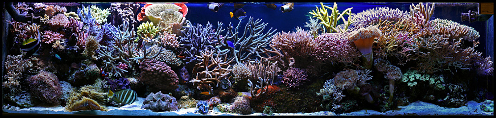 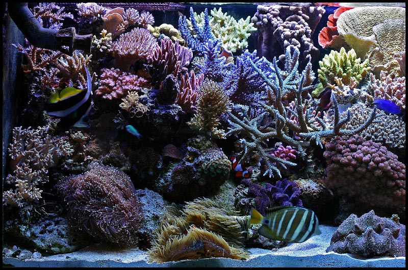 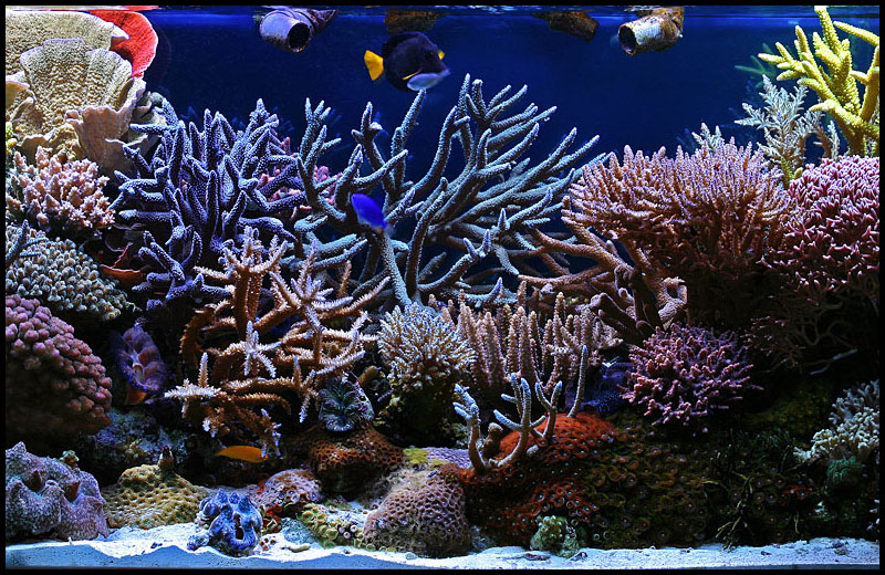 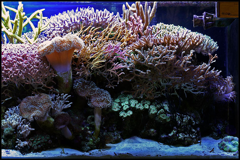 I started the build of what would become the fishroom by tapping into the available plumbing that is part of our master bathroom enclosed in the adjacent wall. This allowed for hot and cold water as well as a sewer drain line for the sink that was to be added. Heres where I added the required plumbing lines after having removed the sheetrock to gain access. 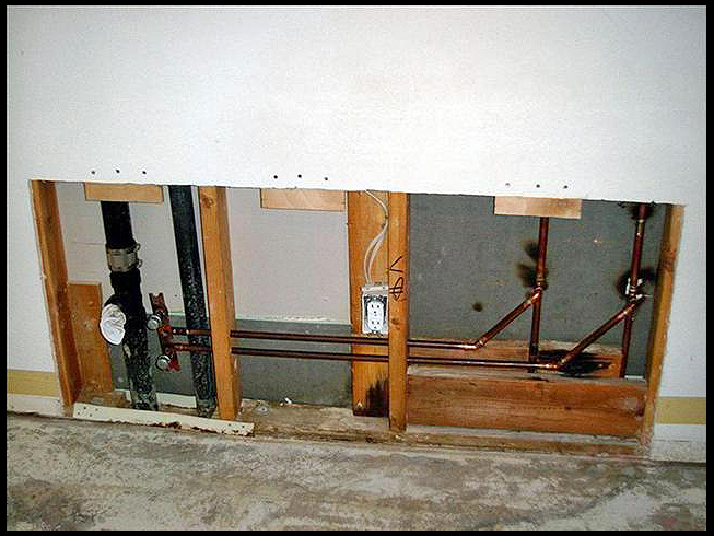 And following is the sink after installation. This included attaching acrylic splash guards to the two walls behind. Note also that this was all done after having stripped the floor down to bare cement (slab foundation) and applied two-part epoxy floor paint. 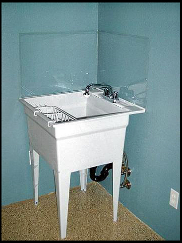
Last edited by weatherson; 09/08/2007 at 12:16 PM. |
|
#12
09/08/2007, 11:40 AM
|
|||
|
|||
|
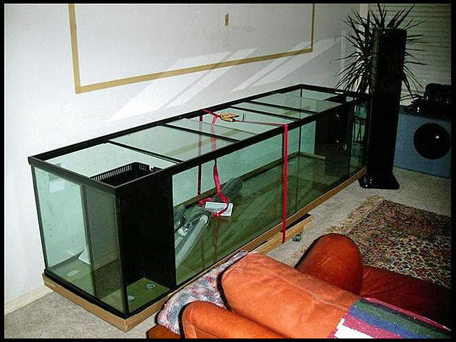
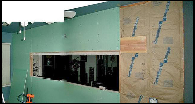
Heres a shot of the new tank seen from its backside. I special ordered this tank with black silicone and two holes on its back glass pane for the two closed loop systems inlets. There is no Starfire glass and the prefilter boxes are their stock units with two holes in each, one for a 1 bulkhead and the other for a ¾ bulkhead. Note the tape on the wall above the tank is the rough cut-out where the tank would eventually be at home.
 Next is a shot of the opposite side of this wall after having removed the existing sheetrock. 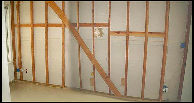 Next, I needed to support this wall temporarily as it's a load bearing wall. On the viewing side, I lag bolted a 2X4 horizontally near the ceiling to which I placed 3 vertical 4X4 posts with jacks beneath. Then I slowly jacked the wall up until there was a good amount of tension. Then it was just a matter of cutting and removing the studs at the point where they would then meet the top of the header (4"x12"). This shot shows the already header installed. 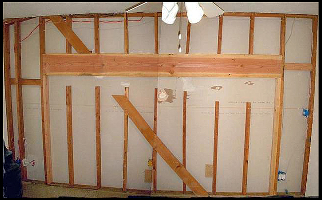 Now, with the tank available for exact measurements, I started creating "the hole" and place the needed wiring with outlets. I ran 2 new 30 amp lines from the breaker box to the double outlet box just to the right of the tank opening. From there I branched each line out to two separate boxes, one above the tank for lighting and the other to the left for other equipment. I also chamfered the bottom edge of the beam to aid in preventing obstructing the lights. Each outlet has its own dedicated GFI. Note that this and other shots were stitched together from multiple shots due to the width of the subject. 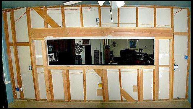 It was now time to start on constructing the stand. I made this of 4X4 and lots of 3/4" plywood for torsional stiffening. If you look at the above studded wall photo, you can see I added several 4X4 verical supports for under the tank. So the wall esentially became one side of the stand. The stand would then be lag bolted to the wall to become "one". Note that the openning is 3/4" taller than the tank to allow for the plywood base that the tank would rest on and that also helped in joining the stand to the wall. Here's a shot of the stand "dry fitted" to the wall. 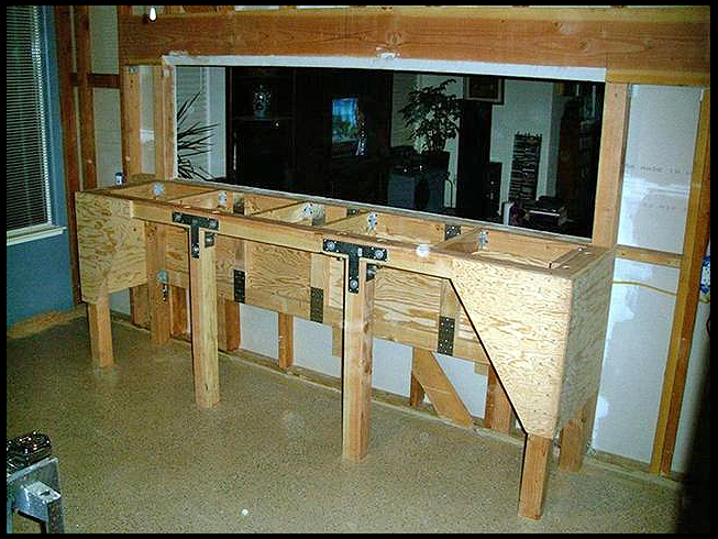
|
|
#13
09/08/2007, 11:42 AM
|
|||
|
|||
|
I insulated this wall to lesson noise transfer into our living room and utilized green bath wallboard.
 And after taping and texturing to match the rest of the room. 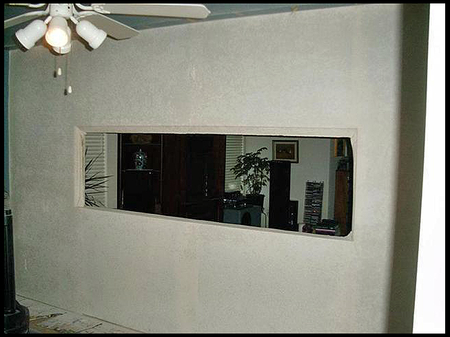 This next photo shows the stand completed, painted and ready to bolt to the wall. Also, the walls were painted and 3" base-boards enamel painted and attached. I then silicone sealed around the room to contain any spills to this room. 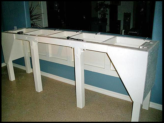 Next we have the stand attached to the wall with top in place. Note the overhang for plumbing, a place to place things while working and a good knee/foot support while salt water swimming. Also, note the paranoid excessive use of screws on the stand. The top indentation is for plumbing routing as you will see in coming photos. 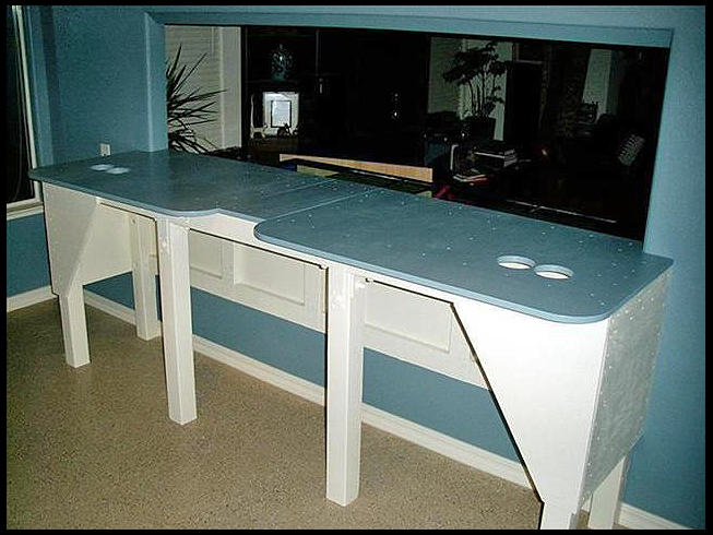 So it's time to place the tank into "the hole". It had to be put in place through the hole, as there was no way to get it into the fish room (this was planned) due to a tight spaced hallway. So here's a shot with it in the right position to be inserted. Looking through the opening you can get an idea of the orientation of the room. Sink at right, entrance to the left and a handy closet in the middle. There's a window to the right of the sink you will see in upcoming photos. 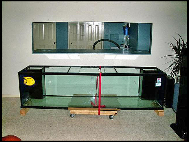 So now you are saying to yourself, "that's going to be a tricky situation get that monster through a hole that has all of 1/4" clearance at the top and sides". True... if not for.... ROBO HOIST!!! Heres a couple shots of it and a couple of the tank in place on the stand.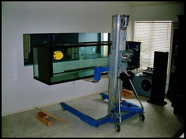 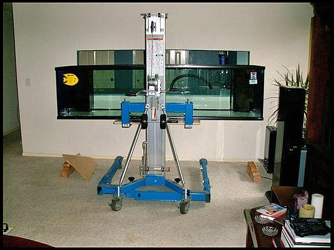 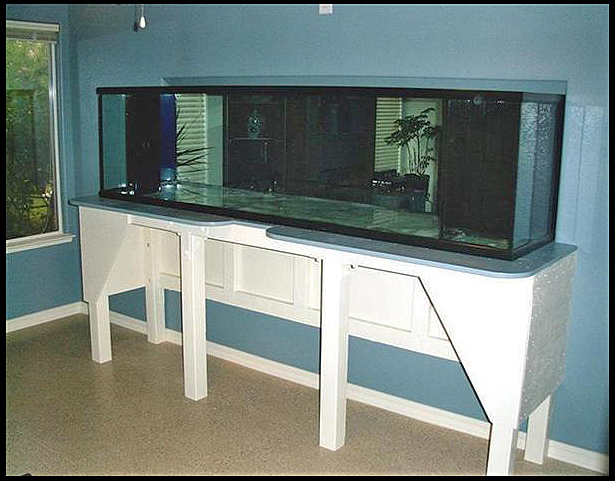 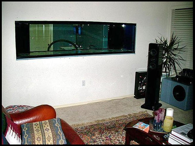
|
|
#14
09/08/2007, 11:45 AM
|
|||
|
|||
|
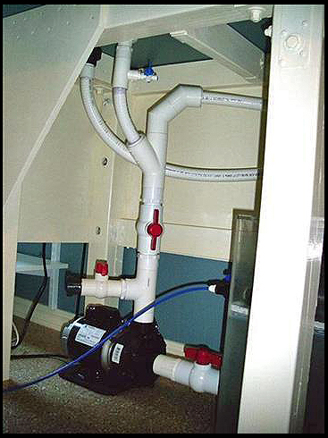
Heres a shot of the original plumbing that I would later change including switching out the AmpMaster 3000 to a Sequence 4300 main circulation pump. The sump is an acrylic 55-gallon tank.
 I then added saltwater and 8 bags of Southdown sand. I set up my old DIY skimmer and ran it for 2-days to remove the Southdown storm from the tank. You can also see the Durso standpipes and closed loop systems in a soon to be changed plumbing orientation. Theres also the shelving unit to the left of the tank that will eventually hold the calcium addition equipment. 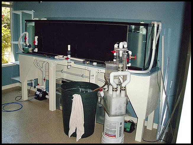 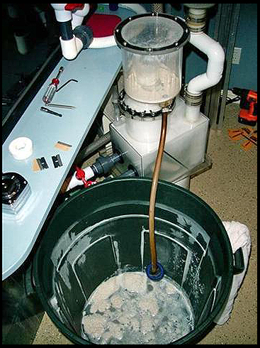 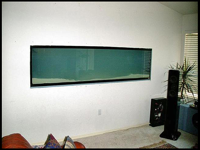 Now it was time to start on the light box that would span the whole tank length made entirely of aluminum. This box would house 4-rows of VHOs and have to leave room for future Metal Halide expansion (two existing 150s were temporarily used) as well as four 25 watt incandescent blue moonlight bulbs. These would eventually be replaced with LEDs. The VHO ballasts, all IceCap, would mount to the top of the box along with two power strips, X-10 controllers and all the wiring. Construction consisted of 1" square tubing and assorted L shaped and flat strips. There would also be provisions for two fans, one at each end and a channel to slide four individual sheets of protective acrylic at the bottom. Here's a photo of the beginning stage, the bare frame. 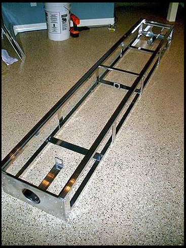 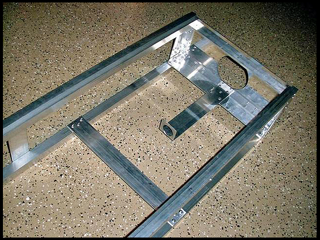 After the polished flat panels were installed 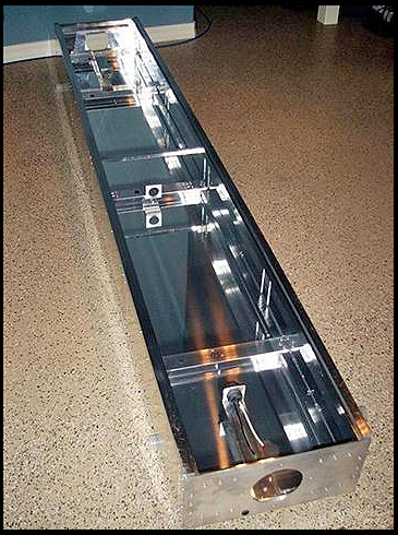 With the bulbs installed and four acrylic covers in place 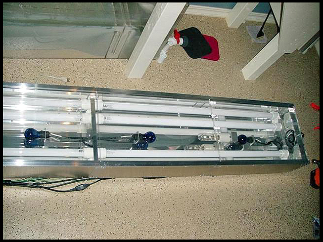 And the top with associated electrical parts and four eye-bolt hangers from which the unit would be suspended 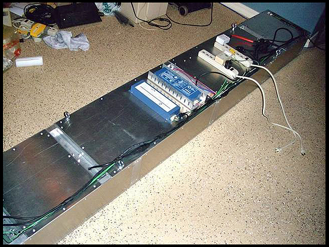
|
|
#15
09/08/2007, 11:48 AM
|
|||
|
|||
|
Heres a shot from the front after having transferred all the inhabitants from the old 65-gallon tank.
The light box pulley system enabling the raising and lowering for easy access into the tank. 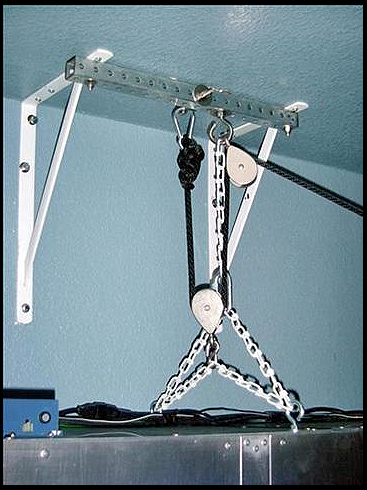 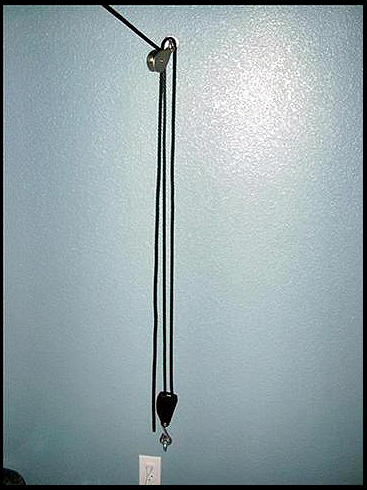 Trim added to the tank front and painted the wall. 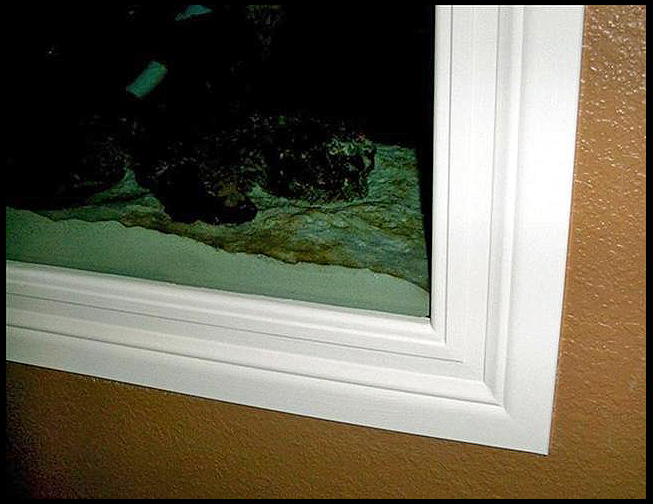 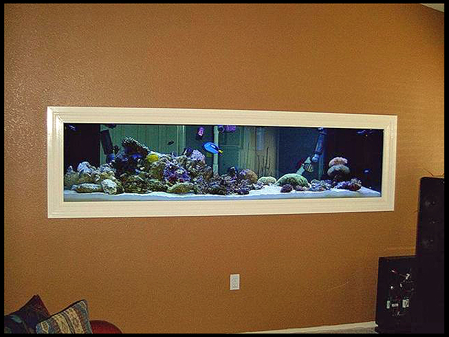 Prefilter box acrylic covers to prevent light from entering as well as lessen noise levels. 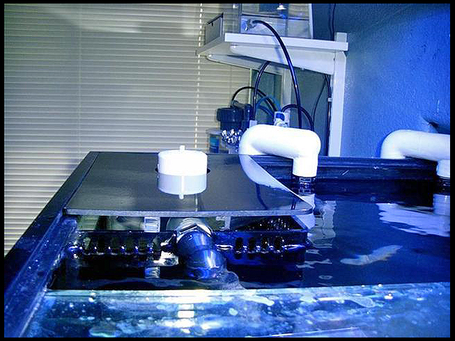 The original aquascaping with dead base rock and live rock from the old tank (circa 9-13-03) and a shot looking down the valley. Look at all that visible rock. 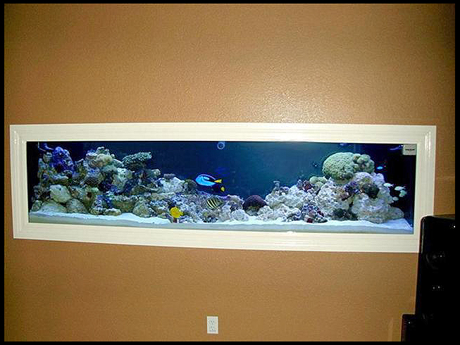 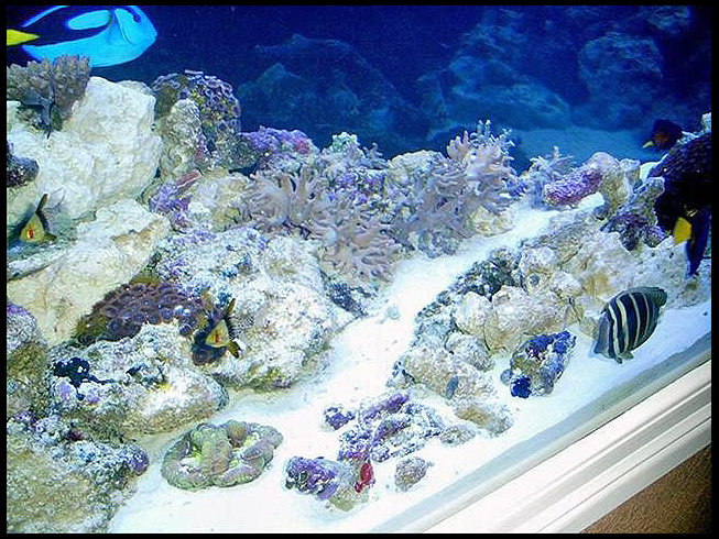
|
|
#16
09/08/2007, 11:49 AM
|
|||
|
|||
|
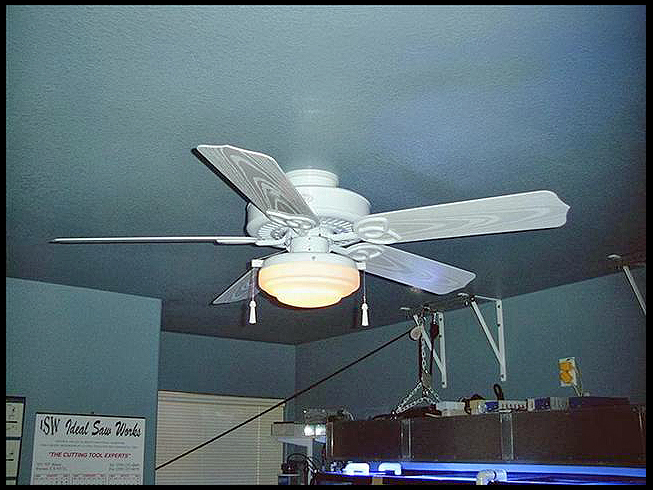
Closed loop drain line for quick water-change tank water removal, weather-proof ceiling fan installed.
  The removable, black acrylic back painted with four colors of paint to simulate looking out into the ocean. The cut-off lower corners are there to accommodate the closed loop systems plumbing. 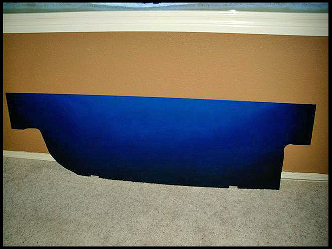 Closed loop systems diagrammed and also showing the backdrop panel in place. 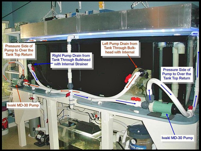 Full tank shot of 12/2/03. 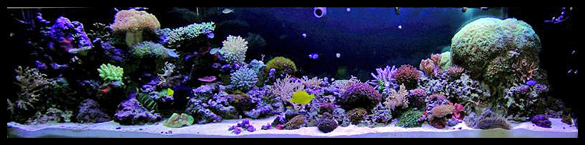
|
|
#17
09/08/2007, 11:51 AM
|
|||
|
|||
|
RO/DI system below the Anti-Cycle Reservoir Device.
More information pertaining to this at
http://archive.reefcentral.com/forum...hreadid=275455 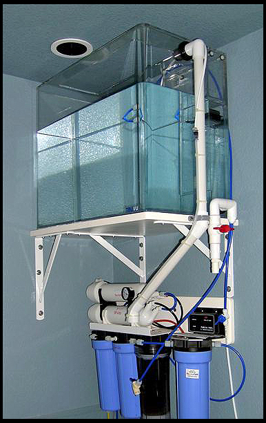 New Beckett injector housings 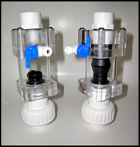 For the new skimmer 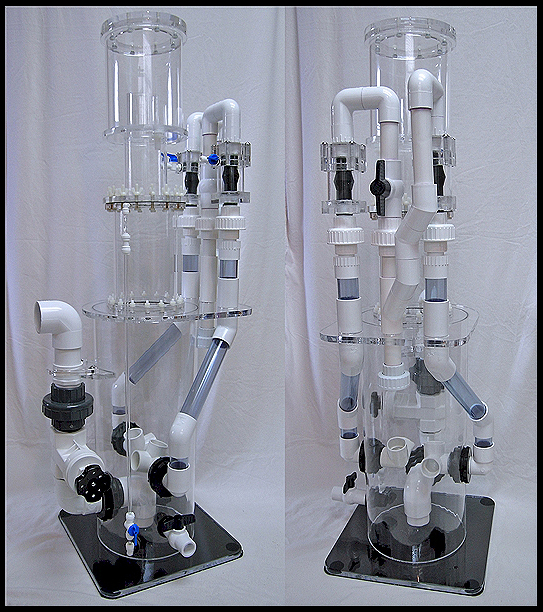 With further information here http://archive.reefcentral.com/forum...5&pagenumber=1 The Lightbox fitted with four DE 250-watt MHs and the original VHOs/25-watt moonlights. The final and current configuration is 880-watts of VHO, three 250-watt DE MHs and two 400-watt MHs. VHOs are all super actinics, the 250s are all Hamilton 14K Kelvin and the 400s are both IceCap 20K Kelvin bulbs. 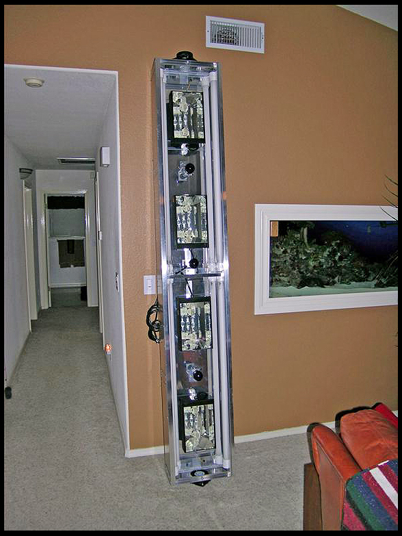
|
|
#18
09/08/2007, 11:53 AM
|
|||
|
|||
|
Full tank shot as of 3/2/04.
 The saltwater mixing tanks diagrams (since replaced containers with larger, 50-gallon, heavy duty units as seen in the third image) 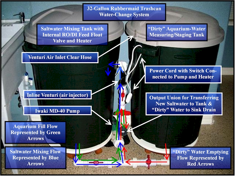 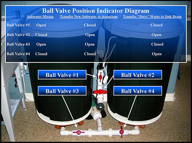 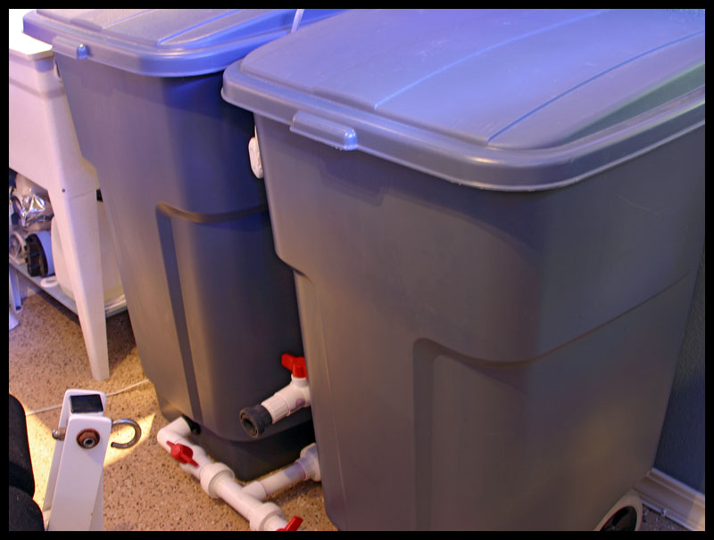 Another full tank shot as of 3/10/04 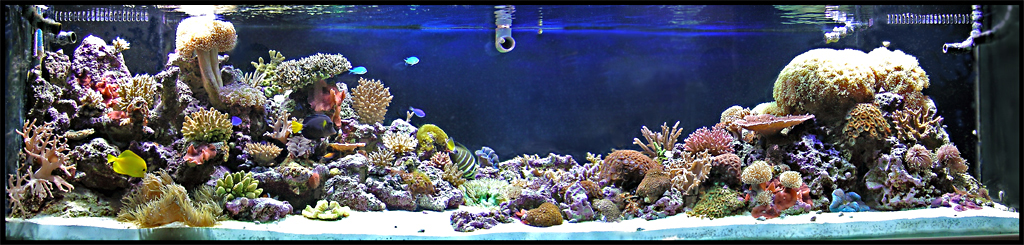
|
|
#19
09/08/2007, 11:55 AM
|
|||
|
|||
|
The making of the Sinusoidal Valve (5/15/04).
The main housing parts and assembled 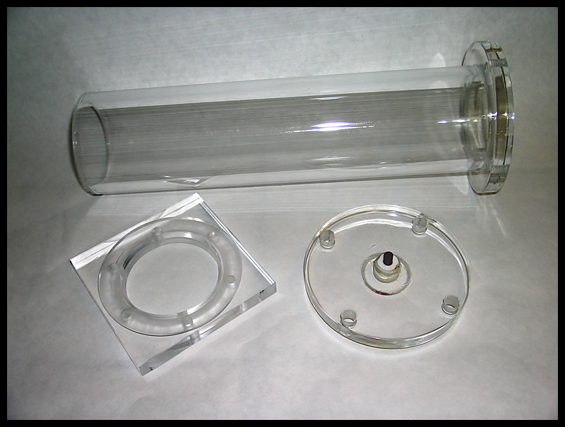 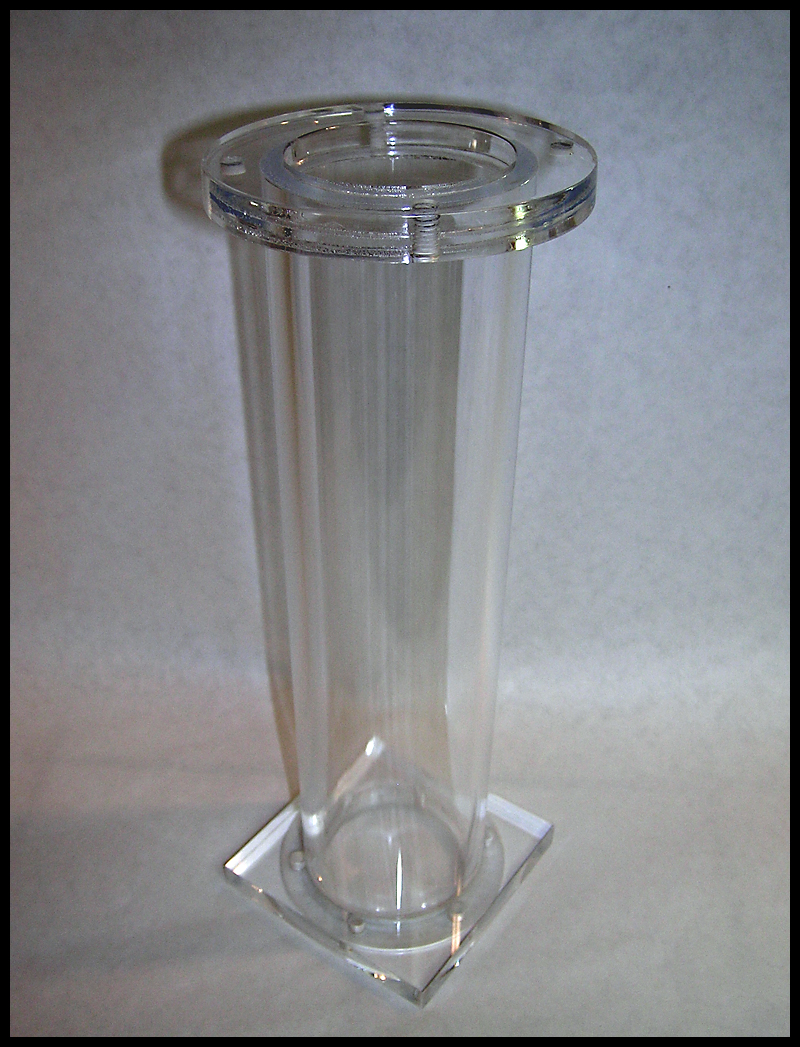 The magnetic drive mechanism parts robbed from an Iwaki water pump.  Assembled unit with 1 RPM, geared motor  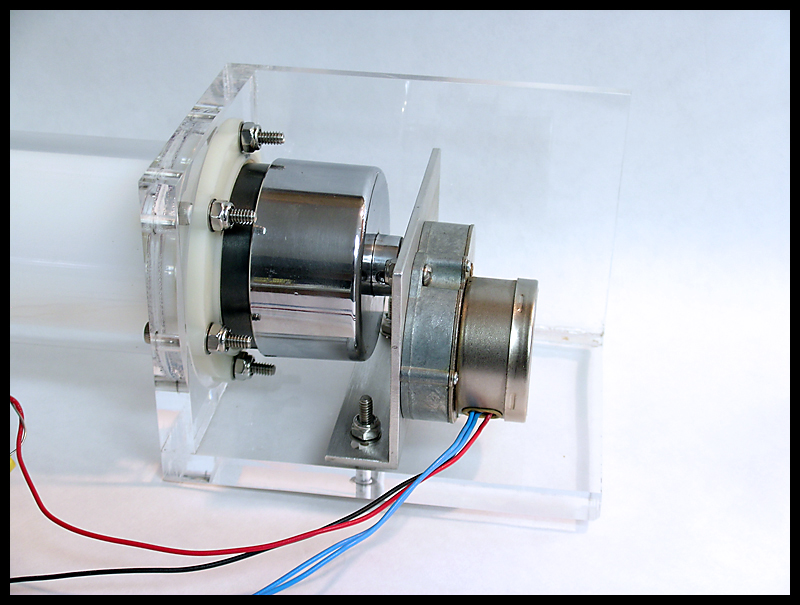 Holes drilled through the outer housing and inner UHMW plastic diverter drum 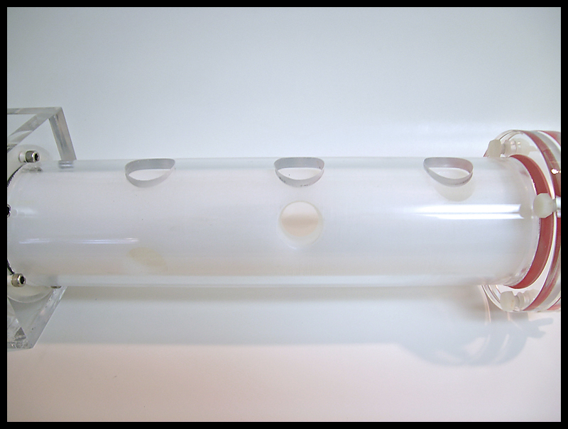
|
|
#20
09/08/2007, 11:57 AM
|
|||
|
|||
|
2 acrylic blocks before and after machining
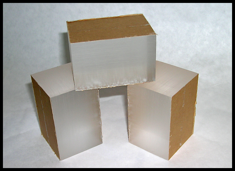 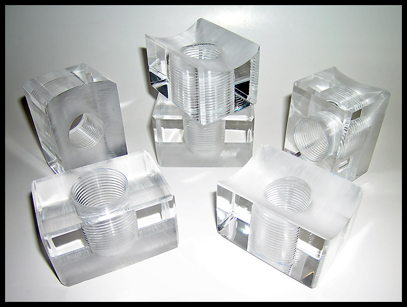 All six blocks threaded to 1 and glued on to the housing 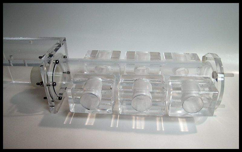 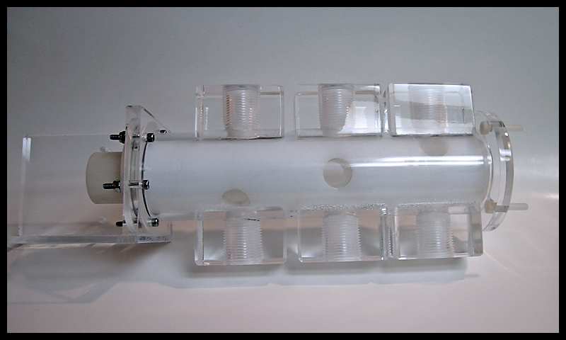 The sinusoidal valve in place with the main circulation flow passing through it 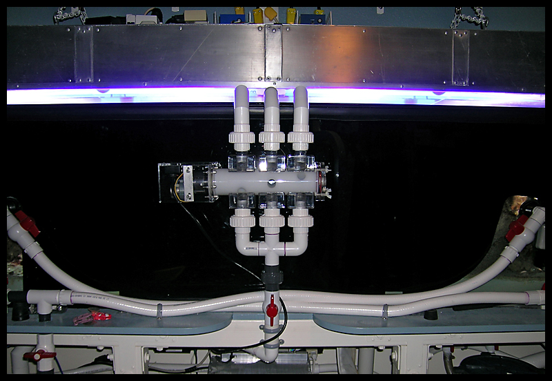 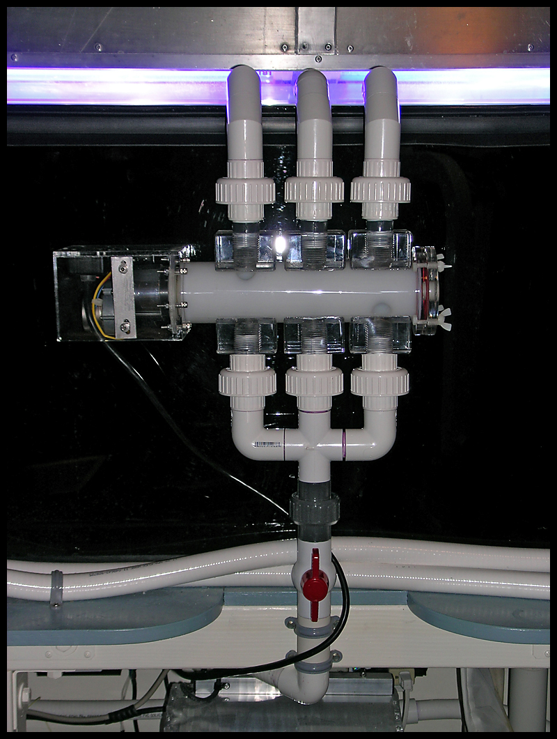 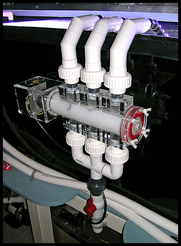
|
|
#21
09/08/2007, 11:58 AM
|
|||
|
|||
|
A full tank shot from 6/20/04
 A slightly dated equipment list but still pertinent power consumption list 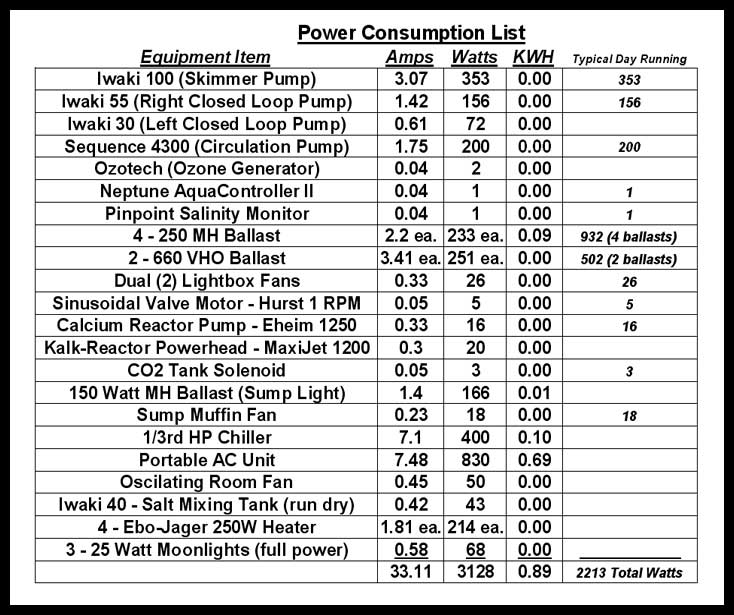 A full tank shot from 8/7/04 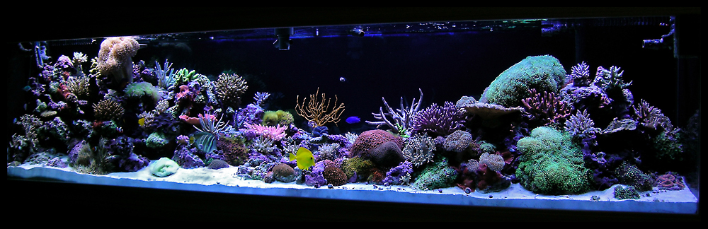 The sump diagram prior to moving the refugium to its own tank and remotely locating the chiller 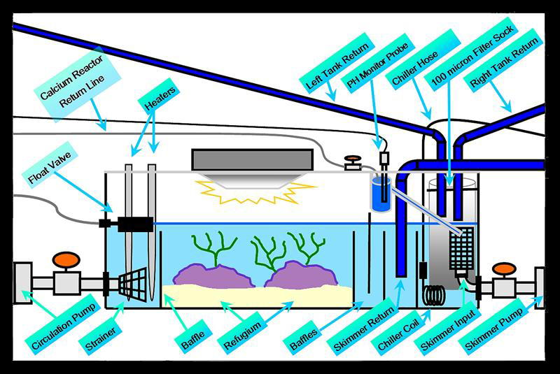 The DIY 20-gallon refugium prior to putting it online. This has a 6500K, 150-watt MH light and mirrored acrylic on three sides (to keep the light in the tank). At the current time, I keep Chaeto growing within and harvest half about every two weeks. This refugium is pretty much completely DIY with having built the tank, stand and light hood. 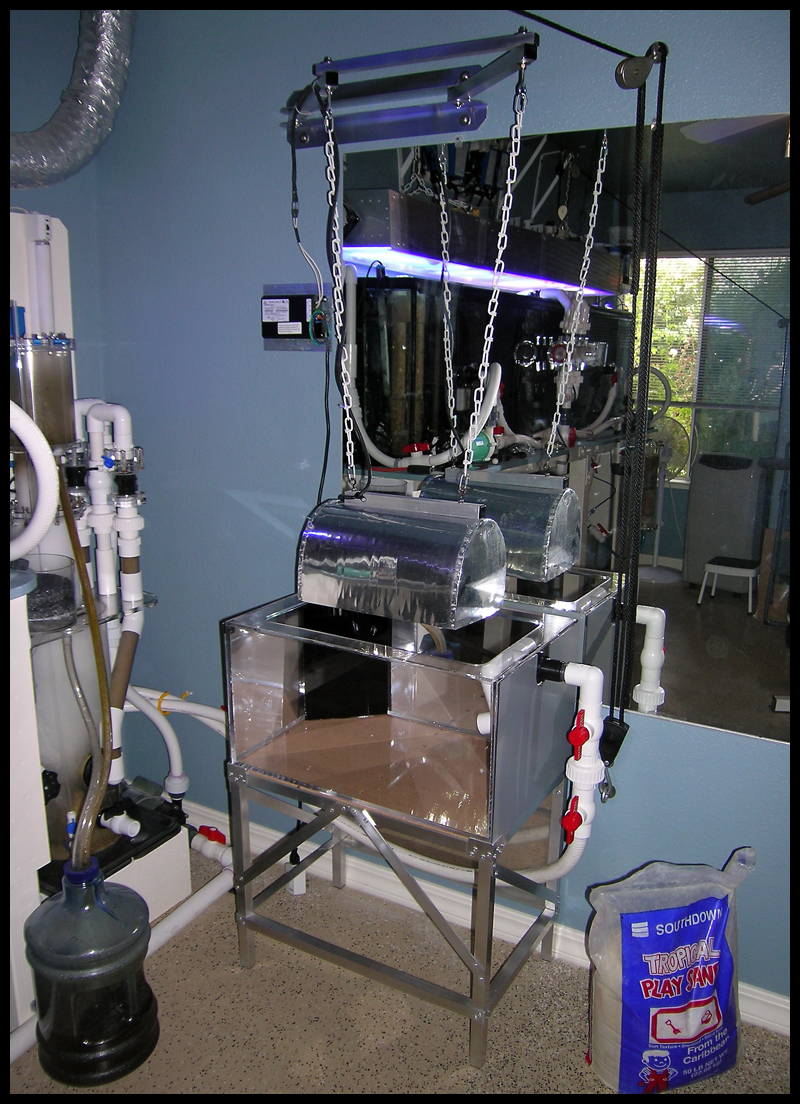 Carbon (DIY housing) and UV filters 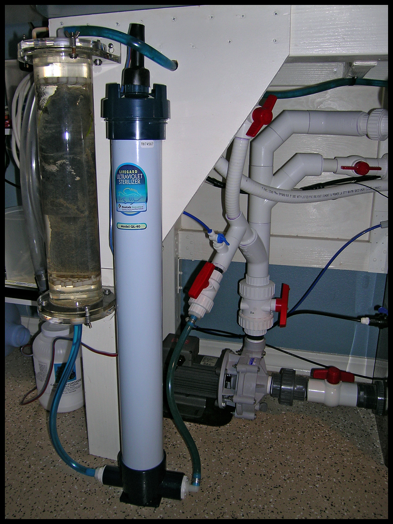 Another full tank shot as of 3/16/05 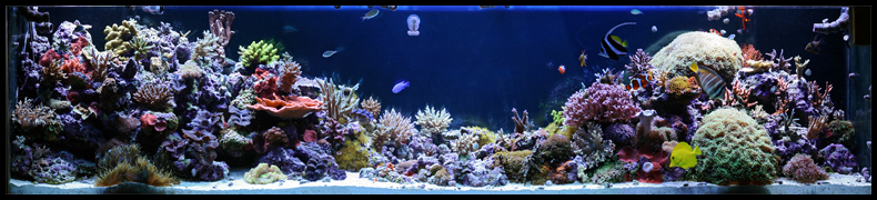 The skimmer inlet air carbon filter 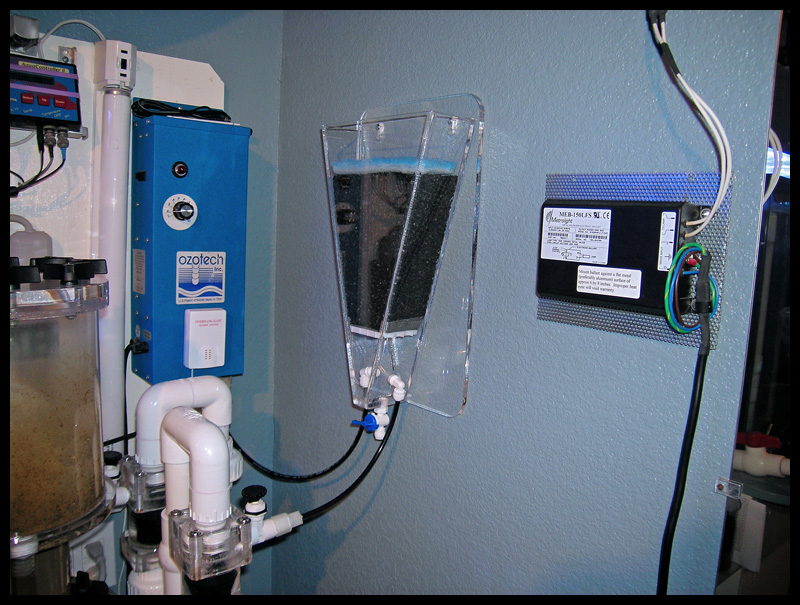
|
|
#22
09/08/2007, 12:00 PM
|
|||
|
|||
|
This section starts the first split section of the thread.
Added Penductors to the closed loops (3/26/05). This shot shows the reach of the flow by having added air to the closed loop for visual representation. 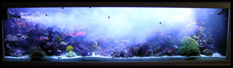 Full tank shot as of 5/23/05 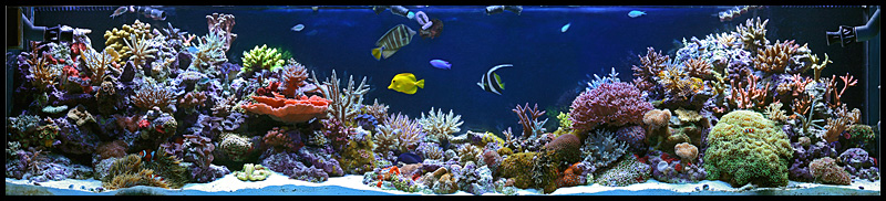 And of 6/18/05 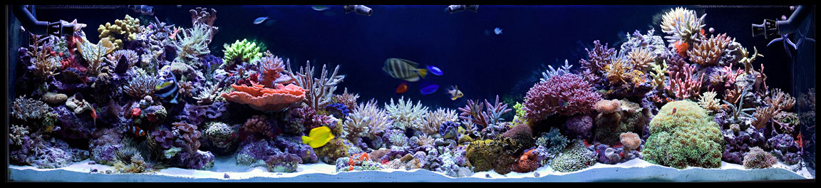 The current light box exhaust ventilation ducting. The tubing protruding from the wall in the first image is where I connect the hose during the winter to capture the heat for aiding in heating the house. 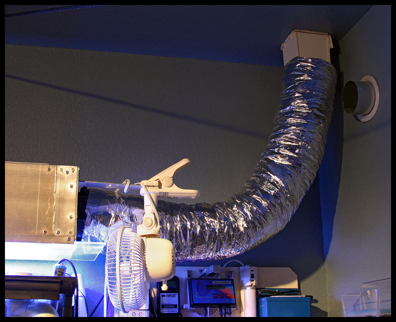 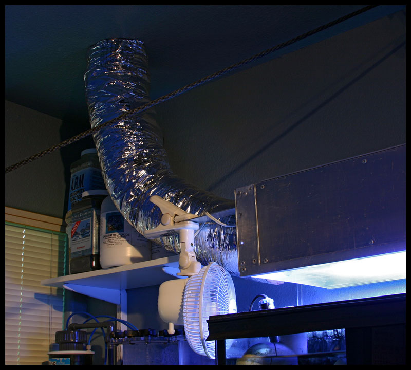
|
|
#23
09/08/2007, 12:01 PM
|
|||
|
|||
|
Converted the stock .75 return lines in the prefilter boxes to also be drain lines for more flow through. Utilizing dual Dursos here.
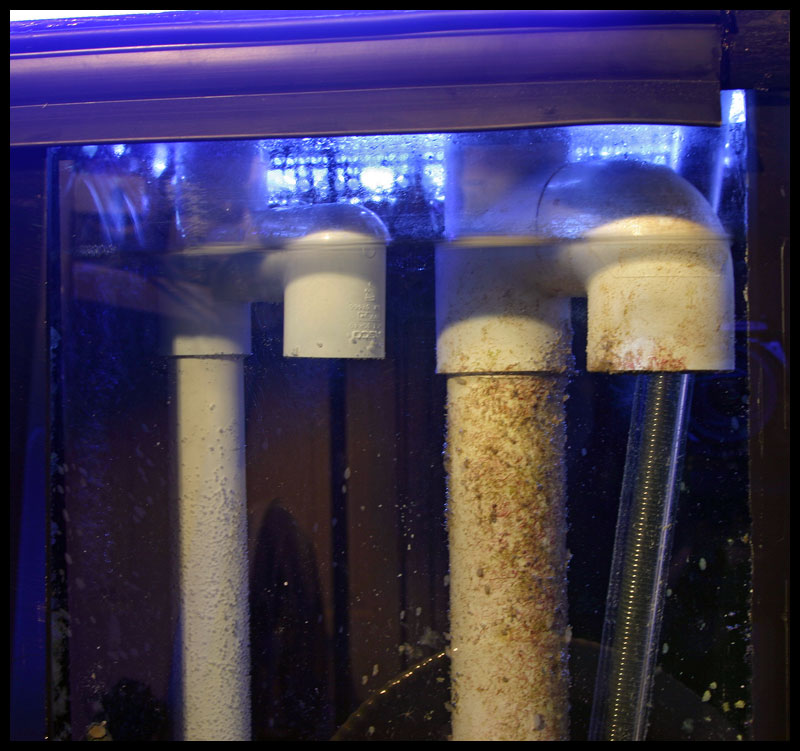 Removed the stock weirs and converted perforated pipe as overflow box guards. 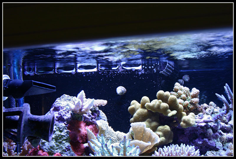 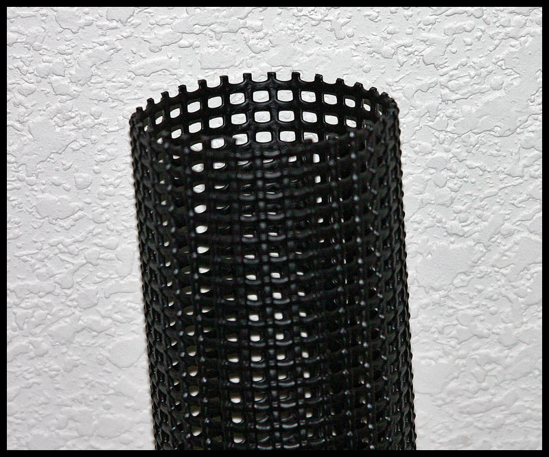 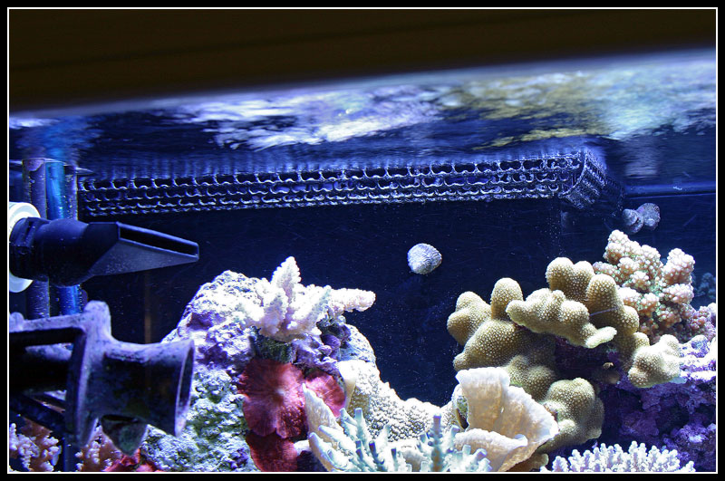 After having had a snail enter one of my Penductors and its shell misdirect the flow severely, I added guards with fishing line threaded through tiny holes drilled in each Penductor. 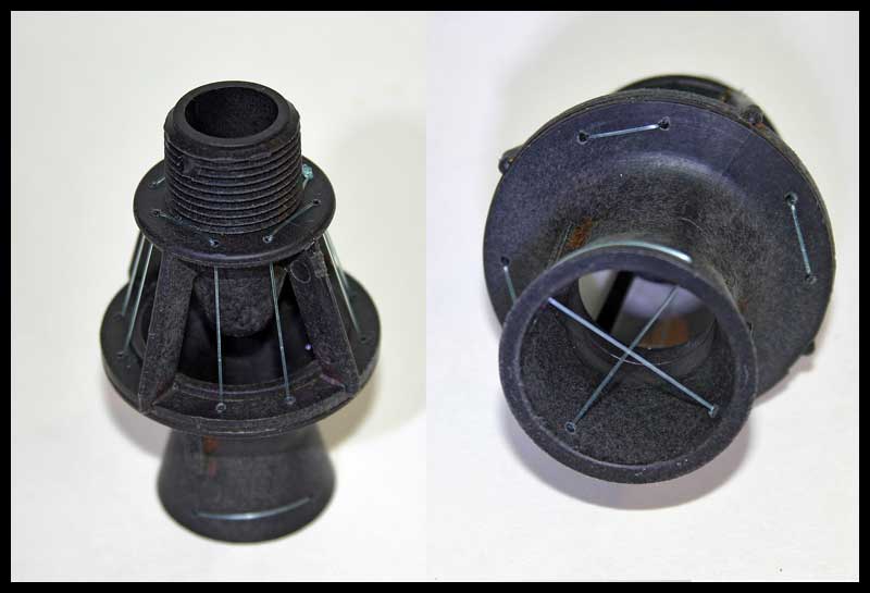
|
|
#24
09/08/2007, 12:02 PM
|
|||
|
|||
|
A full tank shot as of 8/17/05
 The fish trap I built 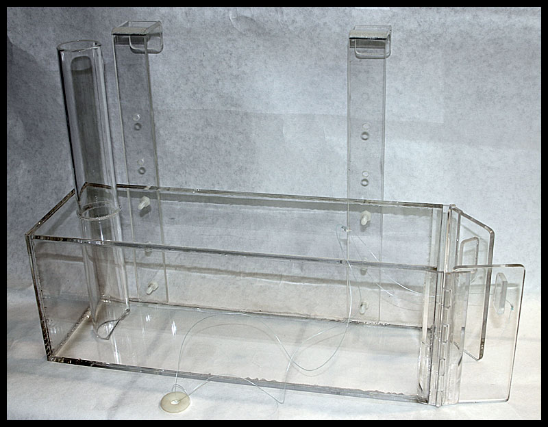 The new Kalk-reactor build (8/27/05) started with heating and forming acrylic for the top and bottom in a form placed in the oven 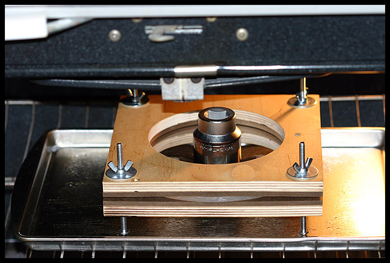 The top 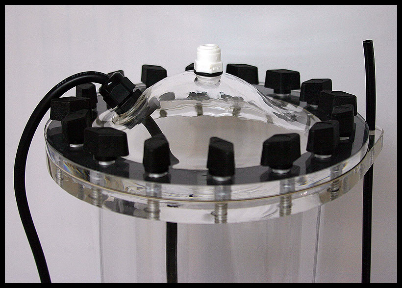 And bottom 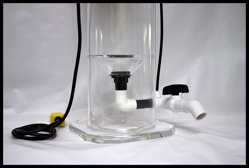 Completed and put into service. Theres a MJ1200 inside that is programmed to turn on for one minute, twice a day to stir the calcium hydroxide. A cord grip device is used to hold the cord at the top and keep this watertight. 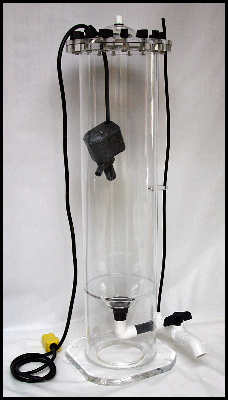 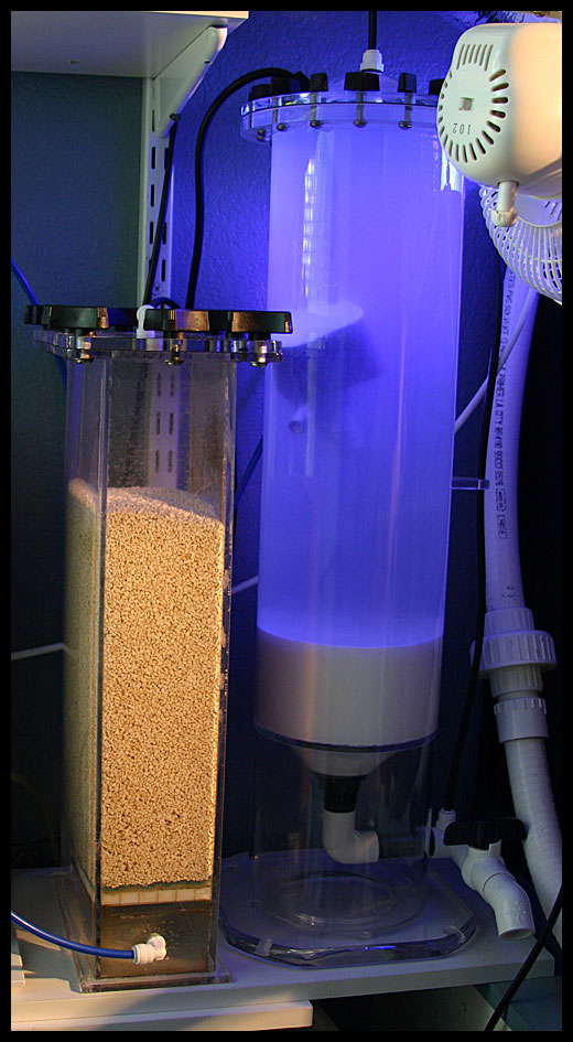
|
|
#25
09/08/2007, 12:03 PM
|
|||
|
|||
|
The new DIY calcium reactor second chamber
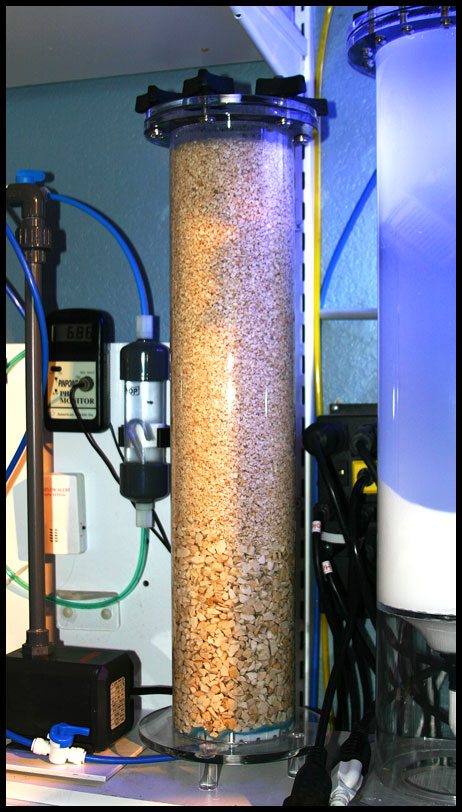 The labeled photo of the backside or equipment side of the tank (9/19/05) 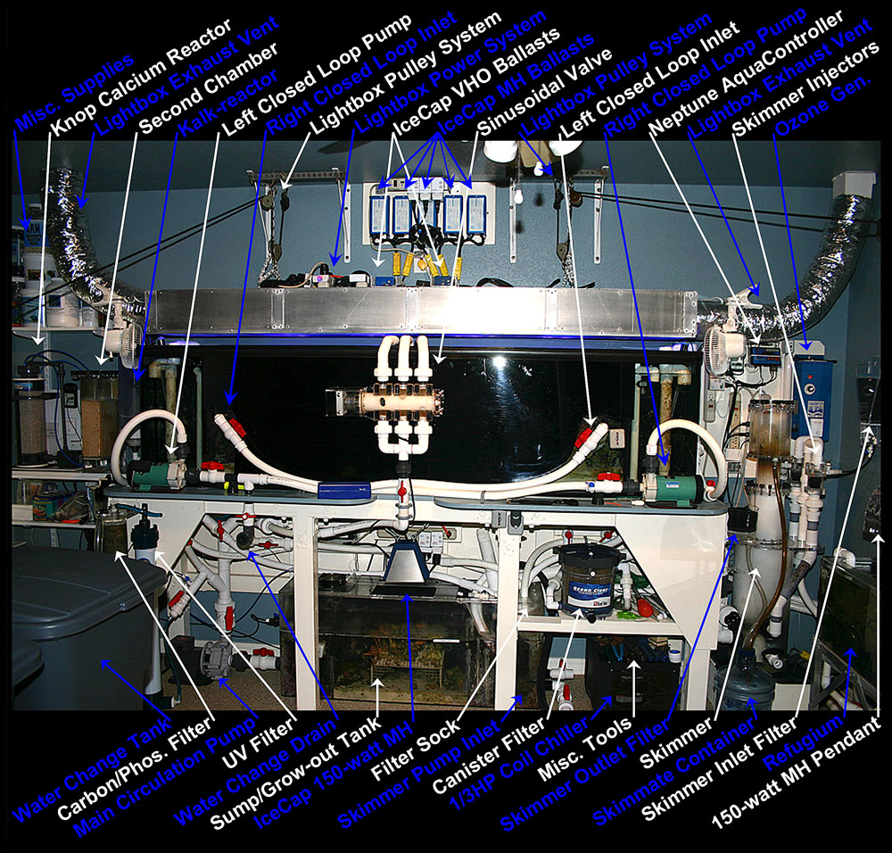 Honored with TOTM for the month of November, 2005 http://reefkeeping.com/issues/2005-11/totm/index.php Full tank shot of 12/14/05 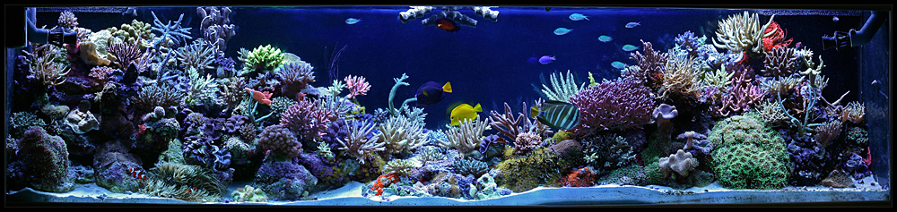
|
|
|


 Linear Mode

