|
|
|
#1
 08/05/2007, 09:50 PM
|
|||
|
|||
|
24 AquaPod Cooling & 120w Light DIY Mods (part 2)
Now for the bulbs and ballasts!
Items needed: 3 straight pin 40w pc bulbs. I chose one each of the following: #2023 40-watt Dual Actinic 420nm/460nm #2024 40-watt Dual Daylight 6,700k/10,000k #2025 40-watt SmartPaq 10,000k Daylight/460nm Actinic 1 - #01763 Current USA Ballast 1x32W, 1x40W (No Enclosure) w/ 4 prong-plug 2 - Bulb clips for power compacts 1 - 4 piece of #14 white braided wire 2 - orange wire nuts 2 - #14 insulated female spade crimp-on connectors 1 - Mini rocker switch (Ace Hdw. # 3135456) 2 - 7/16x1x2 pieces of wood 1 - 7/16x1x1 piece of wood 1 Quick set 2-part epoxy Assorted pieces of mirror plexiglass (you could also use mirrored glass film on clear plexiglass or hi temp flue tape as a substitute.) Tools needed: 1 - each #1 & #2 Phillips screwdrivers 1 - slotted screwdriver 1 - wire crimping and stripping tool 1 - Dremel tool w/bits and/or a utility or X-Acto knife and plenty of sharp replacement blades 1 - propane torch or some other means to heat the knife blade to melt-cut plastic 1 narrow tip felt marker 1 drill w/bits We will be making room for the third bulb (the metal reflector will need to be moved back), add the third ballast, rewire the hood, reposition the bulbs and then apply mirrored plexiglass to the hood. You will be using your existing two ballasts for the new 40-watt bulbs. Dont worry; they will work fine with the higher watt bulbs. This has been well documented on many forums and I have personally used the 40w bulbs with the factory ballasts for almost 20 months. We will be working on the back of the hood. If you are continuing from part #1 (cooling), great! If not, go back to part #1 for disassembling the hood instructions, then proceed to the directions below. 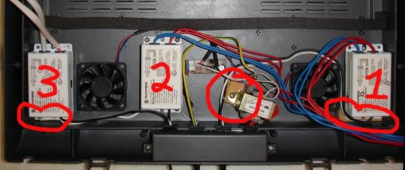 1# ballast will need to be moved down to the lower right corner of the hood. What I used to mound the bottom of the ballast is a 7/16x1x2 piece of wood, (you could probably use a doubled up yard stick epoxied together). I epoxied the piece of wood to the bottom right corner of the ballast area. The wood will be used to screw the bottom of the 1# ballast to the hood and you will use the stock screw post for the top of the ballast. 2# ballast will remain in the stock position. For the 3# (new) ballast, we will move it back to the lower left corner. Follow the same steps as the 1# ballast. Lastly, I moved the transformer to the bottom using one stock screw post and another epoxied piece of wood to remount it to the hood. 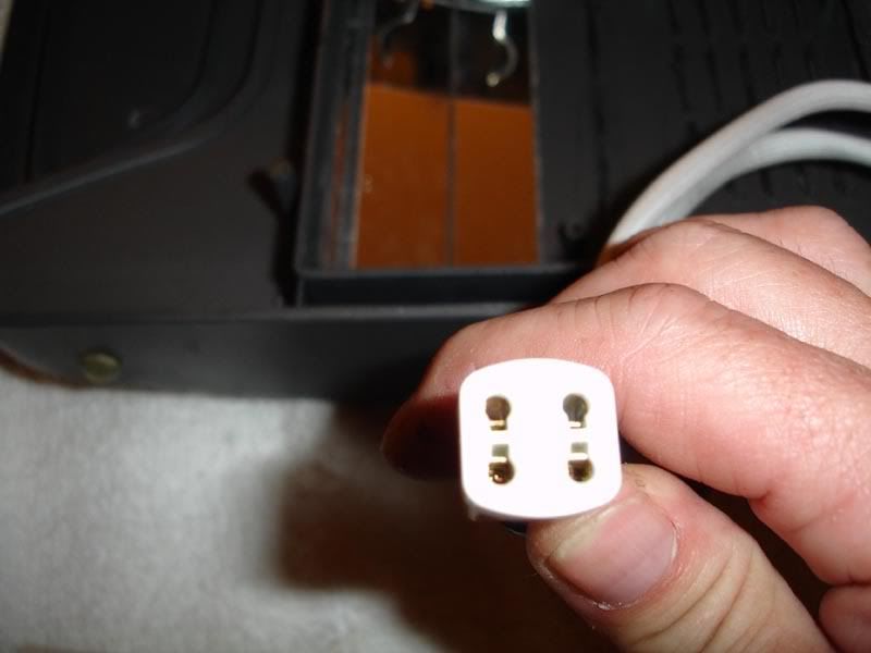 This photo shows the four-prong plug that came with my new ballast. This prong saves you the price of a bulb endcap and also saves a lot of space when you are to reposition the bulbs! For the rewiring, I elected to use the same power cord that also powers my daylight bulb and ballast. I could have used a separate power cord for the third light, but I couldnt stand the thought of another timer to deal with! I did install a fourth switch in the top back of the hood. This was done as a safe guard to control excessive heat in the summer if needed. To access the wiring (junction box) you need to remove the two screws and cover at the bottom center of the hood. Before you start wiring, you will also need to slip the two wires from ballast #3 through one of the rubber grommets into the junction box. Please note: All AC wiring is colored coded; black is hot, white is neutral and green is the ground. Black or hot is what is always switched to turn anything on or off. To my surprise, my pod was wired with the white wires switched! After further testing, I came to the conclusion that they had wired the white wires as hot and the black as neutral! The bottom line is you need to check which wire color Current used to switch your lights. If they are white, follow the below instructions exactly! If they used black, you will need to change the color descriptions for the instructions below! You have everything unplugged right???? Ok, lets start, first cutoff the wire nut from the black wires connecting the power cord to ballast #1. Then strip off about ½ of insulation from all three black wires; the power cord and the two black wires from Ballast #1 & #3 and connect all three black wires securely with a orange wire nut. Next locate and cutoff the wire nut from the white wires connecting the power cord to the switch for ballast #1 and again strip both wires. Then cut a 4 length of #14 white braided wire and strip both ends. Crimp a #14 insulated female spade crimp-on connector to one end. Now securely connect the bare-stripped end of the 4 piece of wire to the two other previously stripped white wires with an orange wire nut. Finally, strip and crimp a #14 insulated female spade crimp-on connector to the white wire from the 3# ballast. 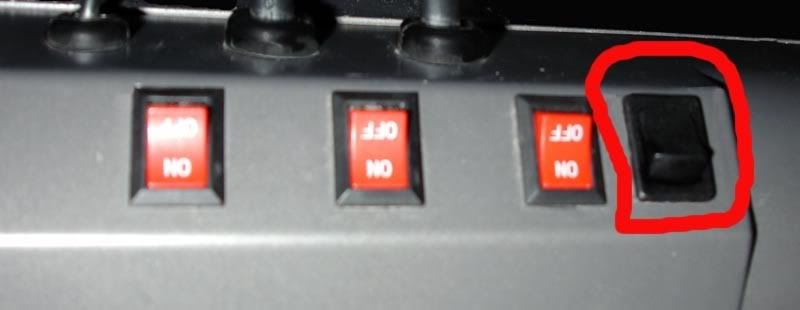 Now flip over the hood. Cut a ¾tall x ½wide for the rocker switch. I used both a Dremel with a cutting wheel and a hot knife to cut to size. Dont be in a hurry, cut small and keep trying the switch in the opening until it is just the right size. Dont push the switch all the way in to the opening after it is sized. First slip the two crimped white wires through the hole and attach them to the male spade connections on the rocker switch. It really doesnt matter which one goes where. Now push the switch all the way into the opening, locking it in place. Flip the hood back over, neatly arrange the wiring in the junction box (yes they will fit!) and reinstall the cover. Ok, on to installing plexiglass mirror and moving & installing bulbs! To get all three bulbs to fit above the clear portion of the lamp cover, the front bulb will be hanging partially over the front of the metal reflector. You need to install something to reflect light off the back of the bulb compartment. I epoxied mirrored plexiglass to the front and top of the bulb compartment not covered by the metal reflector. 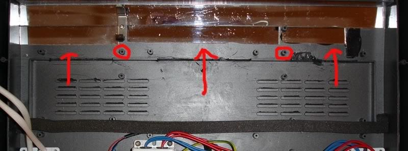 The arrows show where the plexiglass mirror was installed. The circles show the screw posts that you will mount the metal reflector using the reflectors factory front predrilled holes. Note above the left circle, the bulb clip for ballast 1# is already mounted in one of the old metal reflectors front mounting screw post(again, all photos were take after the mod was complete.) The back of the metal reflector will not be attached with screws. The pressure from the foam partition wall underneath and the foam on the top back of the reflector held against the clear lamp cover will hold it in place. 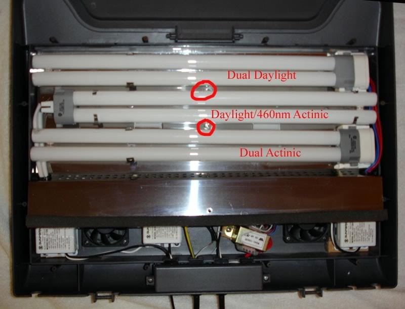 This photo shows the layout I used for the bulbs, end caps/plug and bulb clips. The circles show where I moved the moonlights. To determine the final location of the bulb and bulb holder, you will temporarily attach the metal reflector to the hood, route the lamp wires through the reflector and attach the bulbs to their holders. Arrange the lights to your liking and mark the bulb clips and holders with the felt maker. Also mark a spot between the bulbs for your moonlights. Remove the bulbs from the clips and holders. Place the clips and holders back where you marked them on the reflector and mark the holes to be drilled. You may be able to use some of the factory holes. When drilling the holes in the metal reflector, place the reflector solidly down on a piece of wood that you dont mind drilling holes through. If the holes become jagged or bent, gently take a hammer and tap them flat from the backside of the reflector. If them are still bad, you may need to do some mild grinding with a Dremel or a flat file. 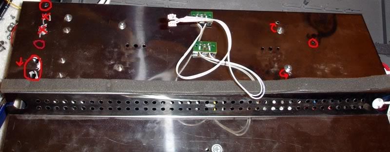 The above is a view of the back of the reflector. Starting at the lower left is the location of bulb holder for ballast #2 (you can see the old holes for 32w to the right). Going up from there you will see the location for the one of ballast #3 bulb clips. As you continue up the left side, the two red Xs are the old location of one of the bulb holders when I first moded the hood for (2) 40w bulbs. The last hole is for the Ballast #1 bulb holder. Because of space constrains on the metal reflector, I only used one machine screw to secure the bulb holder. In the upper center of the photo you will see where I relocated the moonlights. I didnt use the machine screws to mount the moonlights. I simply drilled one hole and epoxied them into place. (This also gave me extra machine screws to fill the old holes.) Moving to the right, you will see two arrows showing where the old holes (filled with the extra machine screws from the moonlights) and pointing to the new holes where #1 & #2 ballasts bulb holders will be located. Lastly the far right hole is the location for #3 ballasts second bulb clip. 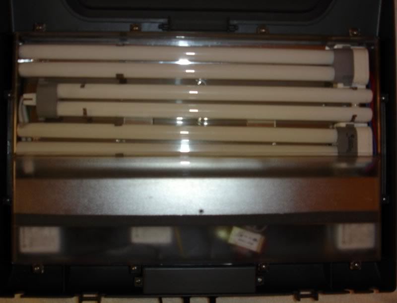 Now lets bolt down all of the bulb holders and bulb clips. Next, plug the moonlights into their circuit board and then position the reflector inside of the hood. Now, make sure the fan and ballast wires are tucked neatly away from the foam partion wall or not covering the fans. Then mount the metal reflector with the two screws and mount the bulbs into their holders and clips. Before you put the bulb cover back on, gently pull up the back of the reflector and double check that none of the ballast or fan wires have repositioned themselves. Dont forget to reconnect the ground wire to the reflector and the finally put the bulb cover back on. Plug it in and see if it works!!!!!! 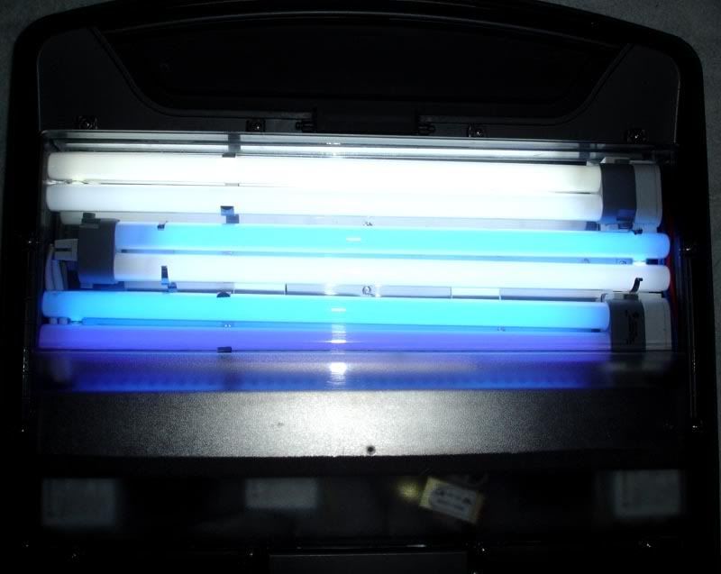 This is what mine looks like! I hope this DIY is helpful for anyone planning an inexpensive cooling & lighting upgrade for their 24g AquaPod. Im sure this type of article has been somewhere posted before, but I never could seem to find one.
__________________
Visit our Club site: http://nwreefsociety.com |
|
#2
08/05/2007, 10:59 PM
|
|||
|
|||
|
Nice writeup.
I did a similar upgrade with a 4 x 32w on my AP. SBC
__________________
i'm gonna sit here all freaking night if i have to just so i can own page 2 of this thread - Nina51 it'll make a turd - Minuteman This thread is just about to be closed - Anemone |
|
#3
08/06/2007, 09:07 AM
|
|||
|
|||
|
Sorry I should have added a link to part #1 (cooling)! Here it is:
http://archive.reefcentral.com/forum...2#post10490722
__________________
Visit our Club site: http://nwreefsociety.com |
|
|


 Linear Mode

